

Introduction: Waren's L.E.D Music Visualizer


Another basic Arduino project is waiting for you to build! This exciting project will allow you to create an awesome L.E.D Music Visualizer using few components such as a Microphone module, resistors, L.E.Ds, and Arduino. This project is perfect for those who really loves music. Everybody loves music (including me) so that's why I made one for my own entertainment purposes. Basically, this project will convert the sounds into lights. Yeah, that's the only purpose of the project to convert the music into reasonable lights so we are able to visualize what the music is all about. For example, if the music is a kind of Dance genre then the music visualizer will convert the music into dancing lights animation effects (pretty cool stuff). Another example, if it is Rock music the corresponding output will be rocking light effects. Is it cool enough to have this kind of stuff in your home? For me, it is yes!
If you have no time to read this whole documentation in creating your own Music Visualizer please watch the video tutorial I've provided. For a great detail in making this project, I recommend to you to take your time to read this documentation. Plus, this documentation has detailed photos to guide you through the project without getting errors or problems. Please consider subscribing to my YouTube Channel for more future updates and projects.
My Inspiration
When I am browsing on Youtube to watch some interesting Arduino projects, I found something that really inspires me to make one for myself. Yeah! I found this video and I really like it so that's why I started this project and make my own version to play the same song. Owl City - Fireflies is my dedicated song for this project (I am proud that I am certified HootOwl). I ended up with this video for my own version!
How does it work?
Basically, the project is powered by Arduino a very popular microcontroller for all makers out there. For this project, I only use Arduino Nano (why I am still using this? you know the reason why I am always using this stuff in every project that I have because it is small, same performance as Arduino Uno and the important thing is... it saves space.) to serve as the brain for this project. The ear of our project is the Microphone Module, the only task fo this module is to detect the sounds from somewhere and converts it into numerical values.
Here's the process on how the sounds will convert into lights. The Microphone module receives sounds then the sound will be recorded into numerical values. Then the Microcontroller will read the numerical values to check if the values from Microphone module reaches the threshold values of every L.E.D in the project. If the sound values greater than or equal to the threshold of the L.E.D then the L.E.D will turn on and vice versa if not.
I setup unique threshold values for every L.E.D so that it will create nice and smooth light animation effects from music, noise or even sounds. So that's it so simple, you can check the code if you want to learn more about the project. If you are already a developer and you want to improve my project please visit the gist where you can contribute and download the code for this project. Any help is highly appreciated.
Do you want it? Let's make it!
I have a lot of fun creating this stuff in my workshop even documenting this project to post here in Instructables. I hope you will enjoy creating this as I enjoy making it. Do you really like it? well, make one for yours! Please follow all the steps here to serve it as your guide to make your own Music Visualizer.
Playing some music!
I made some videos on playing music with my own music visualizer. I have posted it on youtube and I want you to check these videos out! Please subscribe to my youtube channel and please leave a like! Below is the list of some songs I've recorded with my music visualizer. I hope you will enjoy it!
- Owl City - Halcyon
- Owl City - Rainbow Veins
- Owl City - Fireflies (The Extended Version)
- Owl City - Hello Seattle (The Extended Version)
- Cueshe - Pasensya Na (For all Pinoys out there! Yey)
The Extended Version
The extended version is composed of two Arduino (Nano and Uno) to run. It is composed of two layers of L.E.D just imagine two set of music visualizer with different threshold ranges. Then I add RGB L.E.D to this version to add some little effects in the music that I am listening. So this version is customized and I don't need to make a tutorial for it because this Instructable is the fundamental idea of it, you can make it your own extended version and please tag me in your project!
Inspire me!
I invested my time to work on this project. I give all of my effort to make this happen. Hours of documentation and editing. I am sharing this stuff on the internet to help others to learn and entertain with this simple project for free. This time, I need your help. By voting this project you are inspiring me to create more useful and basic Arduino projects to be shared publicly without any cost. I believe that knowledge is power and free. A little vote is a big help to me to continue my journey here in Instructables. So yeah don't forget to vote this project here in Instructables. Just click the orange vote button in the top right corner of this project and also click the little pink heart above. Also, follow me here in Instructables for more future projects! Thank you so much for your support.
Sponsors
This project is made possible by ConnectedCities and Hive Electronics. For the complete kit for this project, you can check out their sites. Support them because they are supporting me. I made this project even if I don't have enough supplies, tools, and equipment. Also, the quality of images and videos are not considered as high quality. I am using only my smartphone to document my Instructables. If you want to help me or support me, be my sponsor today! I will really appreciate it, with enough supplies, tools, and equipment, I am able to create more tutorials and DIY with ease without worrying about the quality of the documentation. Thank you so much for your support!
Previous Instructables
- The Project E.M.I.L.Y (Electronic Matrix - I Love You)
- The Project E.U.E (Electronic Ultrasonic Emitter)
If you find my previous projects cool, please support me by voting them in the contest. Thank you for supporting me!
This is the time to do something amazing today! Come on, please continue to the first step!
Step 1: What You'll Need


For this project, it requires few electronics components to be able to make your own LED Music Visualizer. All the parts can be obtained from Arduino Starter Kit available from Hive Electronics. Instead of buying the whole Arduino Starter Kit you can also purchase the complete kit dedicated to this project from Hive Electronics. All you need for this project is included in the kit. If you want to support me please purchase the kits from recommended electronic stores (which is my sponsors) such as Hive Electronics and ConnectedCities. Support them because they are supporting me!
You can buy the following parts individually if you live outside the Philippines. The stores are accepting orders only within the country of the Philippines. If so, you can buy these components on your favorite electronics store in your place.
Prototyping Components
- 1 x Full-Size Breadboard
- 1 x Small Size Breadboard
- 2 x Red LED
- 3 x Blue LED
- 4 x Green LED
- 9 x 330 Ohm Resistor
- 12 x Blue Jumper Wires
- 6 x Green jumper Wires
- 2 x Yellow Jumper Wires
- 2 x Red Jumper Wires
- 2 x Black Jumper Wires
- 1 x White Jumper Wire
- 1 x Orange Jumper Wire
- 1 x Arduino Nano with USB Cable
- 1 x Microphone Sound Detection Module
- 1 x 4400 mAh Portable Charger
- 1 x USB Meter (Optional)
Tools
- Screwdriver with Flat-blade bit
Grab your parts and ready the bench because we are going to create something amazing today! If you have some questions regarding the parts list, please comment it below! I am willing to help you! Are you ready to build this stuff? Please go to the next step! See you there!
Step 2: Power the Line


Let's power the line! Oh yeah!
All you have to do is to get your 2 yellow jumper wires and hook it up to the breadboard's power lines. Why are we doing this? Because the full size breadboard is composed of two half size breadboard which is combined into one. So, basically the full size breadboard has two section. The power line in the breadboard is not connected as a whole straight line. They are actually cut in to half. That's why we need to add jumper wires in the power line. Please follow the pictures above on how to extend the power line and act as a whole power line accross the board. After that you may now continue to the next step. See you there!
Step 3: Add Some Lights


Let's add LEDs to the breadboard! Yey!
Get your 9 LEDs to hook up in the breadboard. In my version, I use 3 blue, 4 green, and 2 red LEDs. Don't worry about the colors of LED to be use. It's up to you what colors you will use for your version. Make sure it is 9 LEDs only. If you want to extend the number of LEDs you should modify the code to add additional LEDs to the project. If you know how to write code or extend my code, well, that's cool!
Please check the photos for more details and serve as a guide for your project. After placing all the LEDs please jump to the next step! See you there...
Step 4: Wiring Anode


Here we go, after hooking up all the LEDs in the breadboard, we should add jumper wires for Anode of all LEDs. The Anode is the positive pin of the LED. In my case, I use the 6 green jumper wires for red to green LEDs. Please check the photos for more reference. Then I use 3 blue jumper wires for blue LEDs. Why am I doing this? This is because to make the project consistent and presentable.
Now grab your green and blue jumper wires and hook it up according to the photos I've provided. After adding all jumper wires please go to the next step!
Step 5: I Can't Resist!


We are going to add some Resistor in the project! Why should we add a Resistor? If you want to extend the life of your LEDs well, you need to do this. In my case, I use 330 Ohm Resistor to protect the LEDs and add some brightness to the output of the project. My plan at first is to use 220 Ohm Resistor but sadly I am out of stock. 330 Ohm resistor is not bad because it makes my project slightly bright (not too much bright).
The resistor is directly connected to the cathode of each LEDs and continue to the Ground of Arduino. Traditionally, we are connecting the Resistor to the Anode of LED then continue to the output pin of Arduino. But it doesn't really matter. They are almost the same. You can read more of it here, on what is the difference between connecting Resistor to the Anode or Cathode of the LED. Again, it doesn't really matter if you connect your resistor to the Anode or Cathode pin of your LED, they are almost the same. The important thing is the Resistor must be present in your circuit or else your LEDs will burn and cook into a useless electronic component.
Please follow the photos I've provided to serve as your guide in placing Resistor to your breadboard along with LEDs. When you are done placing all the Resistor please jump to the next step! See you there!
Step 6: Wiring Cathode


Hello there! This time we are going to hook up some wires to the cathode pin of each LEDs. These jumper wires are the wires we are going to hook to the negative power line of the breadboard. In my case, I use all the blue jumper wires left. Go, grab some jumper wires left in your parts case and hook 'em all!
Basically, hook all the jumper wires from the end point of the resistors into negative power line of the breadboard. Please follow all the photos I've provided, make sure, all the connections are working, sometimes these jumper wires are defective. Do some connection test before anything else.
If all connections are working properly please jump to the next step!
Step 7: Preparing Microcontroller


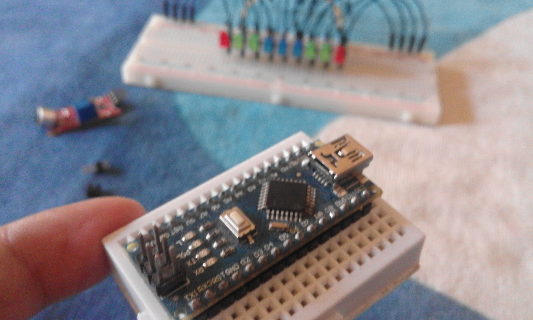
Get your Arduino Nano and hook it up to the small size breadboard. If you don't have Arduino Nano, you can use Arduino Uno. You already know why I keep using Nano it is because it saves space. After hooking up the Arduino Nano to your small size breadboard you can now upload the code to the Microcontroller. Go to the next step, I will guide you where you can get the codes and how to upload it! See you there!
Step 8: Nano Issue Fixing


Before uploading code to the Nano, we should fix first the most common issue in Arduino Nano which is unable to upload sketches from PC to the board. In my previous projects, I provide an explanation on how to fix this kind of issue in Nano. You can check out this specific step in my contest winning Instructable " The Project E.M.I.L.Y." You can read more here about fixing this issue.
To fix the issue in Nano, get your 2 pin jumper and 2 male pin headers. Then connect them as you can see on the photos showing how I connect them. After connecting 2 pin jumper and 2 male pin headers, hook it to the A6 and A7 of your Arduino Nano. Check the last picture for more reference. When you are done doing this please go to the next step so we can now upload some codes!
Step 9: Upload the Codes


Let's upload some codes to the Microcontroller. You can get the codes by using the links below. There are two options in the links below. One is the "Copy and Paste" link which will redirect you to the Github's Gist where the codes are maintained and developed. Then, the other one is direct download from official repository (which is the Gist).
I am inviting you to participate and improve the codes I've made. I am looking forward that this project will improve over the next years. Just make your changes in the repository and give me a pull request. Any contribution would be great!
Now, get your Arduino Nano and plug it into your computer. Use the Arduino Nano USB cable to plug it. After that, check if your Arduino Nano is readable by your computer. If it is not readable, please go back to the previous step and repeat the process in fixing the issue. If it is readable by your computer then you're ready to go!
Check the second photo to properly configure your Arduino IDE. Make sure you're following the setup for Arduino Nano as you can see my photos as your reference. If you don't have Arduino IDE please download it here.
The code comes with debugging and LED testing code which is you can either set it true or false. Please check the third photo for reference. Another thing, you can set your own threshold ranges. By default, I use 500 to 528 analog reading value. Then I divided it into 9 so it will increment by 4 up to 528. This will make your Music Visualizer smoother lights animation effects when exposing to sounds or music
The three last photos are showing the debugging process on how to setup the correct ranges. It also shows how the Music Visualizer works. I will explain in great detail below.
When the readings from the Microphone Module is greater than or equal to the threshold ranges then the LED will turn on. Every LED has unique threshold point which will turn on if the sound value reaches and meets the certain value of LED's threshold. As you notice, the serial monitor is printing the process and you will see when the sound value becomes 500 then it prints the "LED ON."
Not all Microphone Module has 500 default. I adjusted the Microphone Module into ~480 to `~490 range so it can act as the quiet point of your Microphone. I will show you how to adjust your Microphone module in step 13.
The last photo is I am showing to you the Serial Plotter. It prints the data from your Microphone Module. It will show you how it receives the sounds in wave format. It looks like you are playing music in your Arduino IDE LOL.
For now, click the link below to download the codes and upload it to your Microcontroller. If you're experiencing a problem in uploading the codes into your Arduino Nano please feel free to leave your issue by commenting it below. I will try to help you as I can. If you're successfully uploaded the codes in your Arduino please go and jump to the next step see you there!
Copy & Paste the Code
Download the Code
If you want to contribute please feel free to check out my GIST and Contribute to Waren's L.E.D Music Visualizer Arduino code.
Step 10: LED and Mother Ship


This time we are going to plug all the Anode jumper wires of each LED in our Mother Ship (the Arduino Nano what I mean). Get the jumper wires which is connected from Anode pin of each LED. It is composed of 6 green jumper wires and 3 blue jumper wires as shown in the photos.
Connect 'em from D3 to D11 pin of your Arduino Nano. This means from the 1st LED (the Red one) should be connected to the D3 pin of Arduino Nano and so on...
Please check out the photo for more reference. After you doing this please jumper to the next step!
Step 11: Power the Breadboard


Now, get your long red and black jumper wire and hook it up to your breadboard. The red wire will be plug into the positive power line in the breadboard. The black wire will be plug into the negative power line in the breadboard. Next, connect the red wire from the positive power line of breadboard into 5v Pin of Arduino Nano. For black wire, connect it to the Ground or GND pin of Arduino Nano. For a more detailed guide please check the photos.
Jump to the next step!
Step 12: Be a Listener!


Being a good listener can help you to see the world through the eyes of others. It enriches your understanding and expands your capacity for empathy. It also increases your contact with the outside world by helping you improve your communication skills. No no no... this is out of the topic! *technical difficulties...
Anyway, I am not here to talk more about how to be a good listener! If so, please go here. Let's continue making of Music Visualizer!
Grab your Microphone Sound Sensor Module and plug it up in your breadboard then shout out for "Eureka!." Lol, that's hilarious and embarrassing to do hahaha. When you're done hooking your module to your breadboard kindly get the 4 remaining colored jumper wires (1 orange, 1 white, 1 black, and 1 red jumper wires).
Connect the power jumper wires (red and black jumper wires), red for the " + " pin of Microphone Module into the Positive power line of the breadboard. For the black wire, connect it to the ground or "GND" pin of Microphone Module into the negative power line of your breadboard.
Connect the white jumper wire into A0 pin of Microphone Module into the A0 pin of Arduino Nano.
Connect the orange jumper wire to the D0 of Microphone Module into the D2 pin of Arduino Nano.
Warning:
If you get wrong in connecting these wires to the module, the module will produce heat and might be hurt you and eventually will damage your module. To avoid this situation please double check the connections. I recommend to you to check all the photos to serve as your reference.
Yeah! Congratulations you're almost done! Jump to the next step if you think you're clear.
Step 13: Circuit Connection


As I said from the previous step, check all the connections of your Music Visualizer because in a wrong way hooking up wires it will possibly break your microcontroller or your module. I got the same situation when I am documenting this stuff. I plug reversely the power and ground pins of Microphone module and the Music Visualizer stops working and I notice that something happening in my module. It burns my finger when I try to touch the Module. I immediately remove all the connections to it and correct the connection in the circuit.
If you want to avoid such situation please check all the connections you have. Try to compare the connection from my version to your version. Use the photos that I've provided to guide you in connections. You can also check the schematic diagram for this project for more accurate connections. When all of your connections are good please go to the next step! Prepare your power bank or portable charger because we will add the power source for our Music Visualizer so come on, go to the next step!
Step 14: Powering Up


This time we are going to add the power source for our Music Visualizer. For this project, I use 4400 mAh portable charger which is I already used in my previous project called " The Project E.U.E." Plug your L.E.D Music Visualizer to your portable charger using the USB cable for Arduino Nano. The Microcontroller's power indicator should turn on as the Microphone module indicators turn on.
I manage to measure the voltage coming out from my portable charger it ranges from ~4.9 to 5 volts.
I don't want to make some calculations about the battery life of my Music Visualizer because I don't have Multimeter to measure the overall mA of this stuff. If you want to calculate your power consumption, please visit the links below to calculate your own power consumption.
Here's some useful formula in getting DC power.
Voltage (V) calculation from current (I) and resistance (R):
V(V) = I(A) × R(Ω)
Complex power (S) calculation from the voltage (V) and current (I):
P(W) = V(V) × I(A) = V 2(V) / R(Ω) = I 2(A) × R(Ω)
Note: I am not an Electronics Engineer, I am just an Enthusiast in Microcontrollers and I don't have a degree in this field so, if you see some mistakes here please let me know by leaving your comment. If you could help me to find the average operating time of this project please leave it also as a comment below. I will really appreciate any help from you guys! Thanks. You may now continue to the next step. Prepare your screwdriver and let's calibrate the Microphone Module! Good luck!
Step 15: Sound Sensor Calibration


Not all Microphone sound sensor module has ~480 to ~490 sound value ranges. I think some sound sensor modules has starting sensitivity values of ~20 or ~30. It's up to you which ranges would fit your need. For me, I stick to the ~500 as starting threshold and ~480 sensitivity value for standard sound exposure (the quiet part or no presence of sounds).
Get your screwdriver with a Flat-blade bit to drive the sensitivity knob found in your sound sensor module. You can adjust the sensitivity by turning it to the left to increase the sensitivity and turning to the right to decrease. If you can't visualize on what is the current sensitivity of your sound sensor module I would recommend to you to use Serial Monitor available in Arduino IDE. But first connect it again to the PC and use this shortcut keystroke "CTRL+SHIFT+M." You will see the values running on the monitor and try to turn the screw to left and you will expect the increment in the sensitivity readings in your sound sensor module.
Do whatever you want in the value outputs in the monitor. If you're fine in using ~20 to ~30 sensitivity value then, go for it! But please modify also the threshold in the code. So yeah, nothing to explain here it is just common sense. If you can't understand the code or if you have any questions please leave a comment I will try to help you.
For the best result use the sound value ~480 that shows in the serial monitor because the default threshold is 500. If you are okay in this part go to the last step!
Step 16: Enjoy!


Congratulations! You have now your own LED Music Visualizer!
Play some music from your smartphone or from your boombox and see your stuff in action. Whatever the genre you like it doesn't matter give it a try and see how the Music Visualizer responds to your music. I prepare 5 sample/demo to show you how the Music Visualizer works in action. Check out the 3 first videos here in this step because they are the standard version. Then click the Show all items button to check out the 2 remaining video demo for Music Visualizer which is for Fireflies and Hello Seattle of Owl City. The 2 remaining video demos are in an extended version of this project. What does it mean? I use two set of this project and hook it up in the breadboard and they are sharing in the same signal of Microphone sound sensor module in parallel connection. Then I add one RGB LED and hook it up in the breadboard and connect it to the Arduino Uno. I don't want to explain more about the extended version because that's optional. You're free to modify this project and make it larger if you want. Please notify me or tag me in your Instructable if you have the version of this Music Visualizer I will really appreciate it! Thank you!
Outro
I hope you enjoy making this project as I enjoy making it. It gives me a lot of fun documenting this simple project here in Instructables. I am doing this for free for all students, enthusiasts, and engineers out there. This project is perfect for boys, girls or even in between (you know what I mean), I mean for all genders and ages. I know that everyone loves music as I love listening to it (I like electronics music such as Owl City). So, that's why I made this project and share with you what I made. Thank you so much for taking your time to read this documentation and creating your own L.E.D Music Visualizer.
Sponsors
Thanks to my sponsors who made this project possible. Please consider supporting ConnectedCities and Hive Electronics because they are supporting me. You can get the complete kit for this project in Hive Electronics. Then for individual parts, you can get them from ConnectedCities. If you want to help me in my journey you can be my sponsor please contact me via facebook or email.
Support
I spend a lot of hours making this documentation. I want to get paid off my effort doing this stuff. In exchange, you can vote me here in Instructables. Please click the orange vote button above, located in the top right corner of this page. Don't forget to hit the love button and leave a comment about the project. Please consider sharing this project on your social media accounts that would be really great to pay off my effort. All I want is attention and support from you guys to be able to continue my hobby. Follow me here in Instructables for more awesome stuff.
Previous Instructables- The Project E.M.I.L.Y (Electronic Matrix - I Love You)
- The Project E.U.E (Electronic Ultrasonic Emitter)
If you find my previous projects cool, please support me by voting them in the contest. Thank you for supporting me!
Congratulations you've made your own Waren's L.E.D Music Visualizer! Enjoy! Hooray!

Participated in the
Microcontroller Contest 2017

Participated in the
Lights Contest 2017


![Tim's Mechanical Spider Leg [LU9685-20CU]](https://content.instructables.com/FFB/5R4I/LVKZ6G6R/FFB5R4ILVKZ6G6R.png?auto=webp&crop=1.2%3A1&frame=1&width=306)


