

Introduction: How to Make a Model a and Scene Using Tinkercad


Hello, everyone. I stumbled upon this project a couple weeks ago and was inspired to finish an ongoing project that I had put aside so that I could sumbit it into this contest. In this tutorial I will show you how to design your own Model A and scene through many detailed steps and parts, but feel free to stray from my instructions and let your imagination run wild. I spent hours designing my Model A Ford and creating the scene, so I hope you'll enjoy it as much as I did.
I wrote this tutorial at a beginner's level so that students and designers new to Tinkercad can feel confident designing an otherwise complicated build. I will cover basic skills and introduce new ones too, such as using the align tool to match shapes up perfectly with other objects. While making this model I would recommend keeping a photo or several photos of a Model A at your disposal at all times. Looking at photos can help you notice details you may have overlooked or could help you make your design look more accurate.
*Note: I used the metric system to configure the shapes and dimensions since I prefer the metric system while working with Tinkercad. Be sure to switch the units in the grid properties so that your model comes out similar to mine.
Supplies
Computer
Internet Connection
Slicing Software (Cura, Simplify3D, Slic3r, etc) (Optional)
3D Printer (Optional)
Filament (Optional)
Step 1: Part 1: Designing the Frame

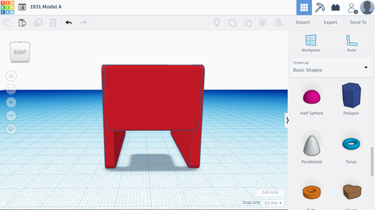
Before we make the scene, I will show you how to design the Model A itself. To start, place one cube onto the workplane and alter its dimensions to resemble the frame of the car. Its length should be 56 mm, its width should be 3.7 mm, and its height should be 39 mm. After applying the proper dimensions, change the radius of the shape in the shape's settings to be around 1.26 to prevent the frame from looking too blocky.
Step 2: Part 1: Designing the Frame


Next we will add windows. Grab two more blocks from the shape selector and change each of their dimensions to have a height of 12 mm, a length of 23 mm, and a width of 19 mm. Set the radius of the windows to be around 2.41. The windows should be placed close to each other and at the same level, but how close you want them together is up to you. Turn these shapes into holes and press them into the original block from the first step. Do not push the blocks in so much that you can see the hole on both sides, just make sure they are pushed into the block without going through. This will create a rim on the window, which will become more visible after step 3. The more that you push the block in, the larger the rim will be. You can experiment to see what looks best on your vehicle. Before moving on, make a copy of one of the window pieces and combine all three shapes (discluding the piece you just made).
Step 3: Part 1: Designing the Frame


This is the final step of part one. For this step, minimize the window that you copied and place it in the center of one of the window spaces. I shrank my windows down to a length of 19.9 mm, a width of 19 mm, and a height of 10.1 mm. After centering them, I duplicated the smaller window and moved the copy to the center of the other window. After lining the windows up, make sure the hole pokes through to the other side, fuse all of the shapes together, make a copy of the entire frame, flip it 180 degrees (making sure the detailed side is facing out), and put it on the other side where the other door would be. We'll worry about the exact placement of the frame later, but for now, keep it on the other side as a visual tool.
*Note: Remember, you don't have to follow my instructions word for word. If you want bigger windows, make bigger windows! Want smaller ones? You can do that, too!
Step 4: Part 2: Adding the Back, Roof, and Floor


Now that we've completed the doors on the frame, we will construct the back, roof, and floor. For this step, place another cube onto the field, resize it to have dimensions of 33.4 mm (length), 3.7 mm (width), and 23 mm (height), and set the radius to 1.49. Place the shape in between the two doors towards the back. You will also need to lift the shape up to the top of the model so that there is a space underneath the back of the car (reference photo for better detail). You may need to adjust the position of the doors so that the back fits inside.
We will also add windows onto the back. To do this, copy the object you just made, minimize it so that it has dimensions of 17.8 mm (length), 17 mm (width), and 6 mm (height), change its radius to 3.1, and make it a hole. Use the align tool to align the window with the back by selecting both the window and the shape and pressing the "L" key on the keyboard. Once you do that, you can use the align tool to place the window in the middle of the shape and using the move tool to move it to the top of the shape. Fuze the back of the car and the window into one shape. Do not combine the doors with the back yet so that the model is easier to work with as you add more parts to it.
Step 5: Part 2: Adding the Back, Roof, and Floor

Now we will add the roof to the car. We may need to remove the roof later in this tutorial, but we'll worry about that later. To make the roof, take two round roofs from the basic shape selector and move them to the build plate. The first roof shound have dimensions of 58.40 mm (length), 36.6 mm (width), and 4.23 mm (height). The second roof should have dimensions of 58.40 mm (length), 36.6 mm (width), and 1.30 mm (height). Rotate the smaller roof 180 degrees so that it's upside down and place the taller round roof on top of the shorter round roof to make the Model A's top. Combine the two shapes and place the roof on top of the Model A.
*Note: The round roof is an actual shape in the shape selector.
Step 6: Part 2: Adding the Back, Roof, and Floor

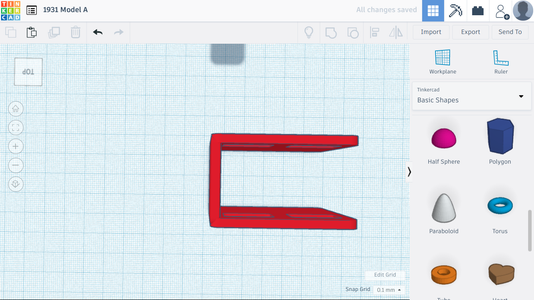
Now we will add the floor. Keep in mind that we may need to extend the floor to acommodate new shapes in the future, but for now we will just tack it onto our design. To make the floor, all that you need to do is change the dimensions of a square to 65 mm (length), 34 mm (width), and 3 mm (height). Place the shape underneath the Model A to finish the floor.
Step 7: Part 3: Making the Front


For this next part I will not yet include the lights, engine, grate, bumper, etc. Instead, I will outline how to add those additional details in a separate section. In this part, we will make a basic front section that we will add on to later and use as a guideline for future steps. To make the front, take a square and make its dimentions 35 mm (length), 31.82 mm (width), and 24.64 mm (height). Take another square from the selector, make it a hole, make each of its dimensions larger than the first square, and copy it. We will need the first hole to mirror the second hole. To do this, we can use the mirror tool. Just select one of the holes, press "M," and use the arrows to flip the second shape around. After that, align the holes (as seen in the picture) so that they will transform the first square into a triangular shape with one of its points flattened. Once you're satified with the triangle, fuze all of the shapes together.
Step 8: Part 3: Making the Front


Now we will make the other half of the front. We will need three shapes: two round roofs and a square. All three shapes should have a length of 33.45 mm and a width of 18.80 mm, but the height for the set of roofs should be 8.28 mm and the square's height should be 12.38 mm. After fixing the dimensions, use the mirror tool to flip one of the roofs upside down, put it underneath the square, and put the second roof on top. Fuze it all together and align this shape with the shape from the previous step. Use the photo for guidance.
After placing the new shape and the shape from the previous step together, fuze them together and move that shape to the front of the Model A.
Step 9: Part 4: Siding for the Tires


This next section will most likely be the most difficult part of the model to construct. Nevertheless, if you follow the steps carefully and pay close attention to the pictures, it should be a breeze. Also, I would recommend doing one side at a time since copying and pasting is more accurate than trying to make one on each side. The first photo is a depiction of how the siding should look after it is complete.
To start, take a rectangle and give it the dimensions 64.59 x 9.57 x 2.27. You will also need two more round roofs. Give one roof the dimensions 31.78 x 10.0 x 16.75 (front) and give the other the dimensions 26.92 x 11.43 x 16.13 (back). Position the rectangle so that one end reaches the back of the Model A, while the other side comes up about half way from reaching the front end (refer to photo). To elaborate, the rectangle should move past the door and come up about halfway to the front. For the roofs, place the small roof towards the back of the car, allowing the rectangle to go through it about half way. Also, make sure the end of the small roof ends up sticking out about a third of the way from the end of the car. For the larger roof, place one end of the roof close to the end of the door, and the other end close to the end of the hood. It should span the entire length of the hood if done correctly. After placing the shape, rotate the shape 2 degrees.
*Note: For the photo I pulled the rectangle out a bit so that you could see its starting point and ending point easier. On your model, make sure that the rectangle is pushed in until it is aligned with the other shapes.
Step 10: Part 4: Siding for the Tires


Now we will add some holes to the siding so that the tires can fit inside. You will need one round roof, one cylinder, and one square for this next part. The roof will have dimensions of 30.98 x 20.00 x 14.53, the cylinder will have dimensions of 21.28 x 26.71 x 20.00, and the square will have dimensions of 20.35 x 20.00 x 10.99. Once you alter each shape's dimensions, make each of them a hole.
We will place the roof hole first. All that you need to do is align the hole with the solid roof in the front, making sure the border wall is still thick and part of the end of the roof has been cut off. For the cylinder hole, place the hole in the middle of the roof shape in the back. Lastly, place the square hole at the far end of the round roof in the back and bring it up so that the hole cuts off a portion of the end of the shape. Do not fuze any shapes together in this step.
You will definitely want to look at the photos for this step. It can be hard to describe exactly where everything goes, and seeing how everything is placed will certainly help you build this model.
Step 11: Part 4: Siding for the Tires


Before we complete the siding we need to add the trunk in the back. To do this, we will need another round roof. Set the dimensions of the roof to be 32.90 x 27.65 x 16.10. Now, place the trunk in the back of the Model A so that half sticks out and half stays inside the car. Make sure there are no gaps above, below, or to the side, and also be sure that the siding on the car comes out farther than the trunk itself (reference photo).
Remember how I said that we may need to extend the floor? All that you have to do is stretch the rectangle at the bottom of the car so that it comes all the way to the end of the trunk. If you start to see the floor sticking out of the trunk, just make the floor shorter (in length, not height) until you don't see it sticking out anymore.
Another thing to keep in mind: if you do have a gap at the top of the trunk, you can increase the height of the shape in the back with the window (shown in green) to cover up this space. After I did this step, the new height for the green piece became 25.60 mm.
*Note: The second photo was taken from inside the car. The black part represents the trunk.
Step 12: Part 4: Siding for the Tires


Now we can fuze all of the shapes together. To fuze them, don't drag your cursor to select each shape. Instead, use "shift" and "click" to select each individual shape. Click on each shape (except fo the trunk) and then hit the group button.
You may have noticed that the side's flat ends look odd. To fix this, get another round roof and minimize it so that the sides can come to a rounded point rather than a quick cutoff. I do not have exact dimensions for this part since the placement of shapes varies from person to person, and even the slightest shift can make a huge difference, so I can only offer guidence for this step.
Basically all that you need to do is take a round roof and squish it down so that it can fit on the ends of the siding. It's best to look at the photo for this step. You may need to use additional shapes to fill in space if the roofs create a problem when you add them on. For example, I used a triangular roof along with a round roof on the front of my vehicle. Don't forget to rotate the shapes so that the siding looks as close to a real Model A's siding as possible.
Step 13: Part 4: Siding for the Tires

Now that we have completed the siding for one side of the vehicle, we can copy and paste it onto the other side. Before you move on, make sure that every component used for the siding has been fuzed together using the shift and click method. Do not fuze the side to the body yet and do not include the trunk when fuzing the parts together. Once you've done that, copy and paste the parts onto the other side. You will need to use the mirror tool to flip the siding around.
Step 14: Part 5: Fancy Features


Congratulations for making it this far! For this next section we will focus on adding details to our Model A. By the end of this section, we'll have exhaust pipes, license plates, grates, lights, mirrors, engines, and bumpers.
We'll start off working on the hood. As you can see, the hood is flat, has a random hump, and then goes flat. Although it resembles the hood of a car, it doesn't look quite right. So, we'll add some triangles and a rectangle.
Start by grabbing a square and a (triangular) roof from the shape selector. Before you apply dimensions to the triangle, rotate the shape until it is flipped like the one in the first picture. After rotating it, give it the dimensions 12.35 x 34.50 x 3.17. Give the square the dimensions 14.20 x 33.58 x 5.28.
I've found that placing the triangles first is better than placing the rectangle first, so we're going to do just that. Take your triangle and match it up with the flat triangle on the hood. Rotate the the triangle so that it adds depth to the hood and more closely resembles the Model A's normal shape. You may need to shuffle it around a little until you get it to the right place. Next, copy, paste, and mirror the triangle so that you can place it over the triangle on the opposite side. Rotate it, shift it, and place it down. For the rectange, just lay it across the middle in between the two triangles.
Step 15: Part 5: Fancy Features


Now let's make the engine. We'll need 4 shapes to make this part: 2 squares, 1 round roof, and 1 half sphere. Make the first square 10 x 10.57 x 7.26, make the second square 5.14 x 11.84 x 4.30, make the round roof 3.35 x 11.84 x 4.30, and make the half sphere 3.50 x 0.73 x 3.50.
Take the round roof and copy, paste, and mirror both shapes a few times. Place the square in the middle and line both round roofs up with it, one on each side. Once you've done that, copy and paste the half sphere twice so that you are left with three half spheres. Attach them to the square and round roofs like in the picture.
After that, fuze all of the shapes and move it to the front of the Model A. Place the first square underneath the part you just made to add detail.
Step 16: Part 5: Fancy Features


Now we'll do the grate on the front of the car. This step might be tricky, so pay very close attention.
Copy the original hood shape that we made in part 3. Drag it to the side and separate the shapes. You only need to separate the triangle from the oval section. Once you've done that, delete the triangle and keep the oval shape. Now, take the oval shape and line it back up with the part on the front.
Now, copy that shape and pull it out a slight bit. Make the shape small enough that it leaves a nicely sized perimeter around the front. Once you're satisfied, make it into a hole and fuze the two shapes together.
Next, grab a sphere from the selector and make it very thin and tall. Move the spheres to the open space inside of the perimeter and use the duplicate tool to quickly make a bunch of the spheres. Select a sphere, hit "ctrl" and "d," and move the shape a few spaces to the side. In this mode you can make the shapes consecutively larger or smaller, move them, rotate them, or a mix of each function after hitting the button again. (The button is located at the top left and looks like sheets of paper in a pile.)
Once you are finished moving and duplicating the shapes, fix their heights so that they connect to either side of the perimeter.
Step 17: Part 5: Fancy Features


Now we can make the lights and mirrors. All we need are two half spheres to make our next shape.
Stick one half sphere to the other half sphere so that they make a ball. Next, squish down one side of the shape so that it resembles the lens on a light. Last, shrink, rotate, copy, paste, and move the lights and mirrors into place on your model. The lights go on the front near the top, and the mirrors go on the sides. Make sure to push the shapes in enough that they are secure and won't fall off if you choose to print the Model A.
Also, be sure to include the lights in the back of the car. They will be much smaller than lights and mirrors, but they have the same shape.
Step 18: Part 5: Fancy Features


- For this part, we will be making the front bumper. On a real Model A, there is sometimes a bumper on the back, but when I built it, I didn't like how it looked. So, we'll only make the front bumper. If you want to make a bumper in the back, feel free to do so.
We are going to need a lot of rectangles for this part. Each rectangle shares a similar set of dimensions, typically something like 1.96 x 15.45 x 1.98, but each dimension may be subject to change as they are fitted to certain parts of the model. Also, we will be needing 11 rectangles for this part.
Start out by taking one square from the selector. Give it the dimensions listed in the second paragraph, copy it twice, and rotate it around 45 degrees. Mirror one of the copied rectangles and leave the other alone for now. Place the two rectangles in the same manner as shown in the photo above.
For the main section, take the copied rectangle and duplicate it 9 times. Stretch, shorten, rotate, and configure each shape in the same pattern as in the photo. Copying the photo will help you most accurately design the front bumper, as it would easiest to show you rather than tell you. Just make sure that the first two parts you made line up with the diagonal rectangles, and the first two shapes fit on the car. Also, be sure that the whole model is not touching the grate from the previous step.
Step 19: Part 5: Fancy Features


This next part will require a secial shape in the editor. The "bent pipe" shape can be found by selecting the "featured shape generators" in the shape selector and scrolling down the first page until you come across the pipe. We will be using this shape for the exhaust.
Take a bent pipe from the selector and bring it to the workplane. You will need to alter the settings for the pipe, and to do that you must look at the first picture above. Once you copy down the settings, rotate the pipe so that it mimics the direction of the pipe in photo three. Now, set the pipe's dimensions to 23.64 x 27.35 x 18.99.
Once you complete that, align the pipe on one side of the car, rotate it if needed, and copy and paste the pipe two more dimes. After setting up the pipes, copy the entire section of pipe by shift clicking each pipe, then pasting it onto the other side. Mirror the section of pipe (with each pipe still selected) and put it onto the car. Make sure the pipes are completely attached underneath the car so that they don't fall off if you choose to print it.
Also, if you want the pipes to attach underneath, you can make the lead out length larger so that the pipe reaches farther across. For example, I made each pipe's lead out length equal to 75. This will help reinforce the pipe for printing.
*Note: Remember, if you don't like the settings or sizes, feel free to spruce it up however you like. You can even move the pipes to a different section of the car if you want to!
Step 20: Part 5: Fancy Features


We have finally made it to the end of Part 5! For this part, we will make the license plate and door handles.
I decided to put these two together since they share a similar shape. We'll do the handles first. So, grab a square rom the selector, give it the dimensions 6.05 x 4.60 x 2.83, and set the radius to 3.79. Line the shape up on the door where the handle would be and place it there.
For the license plate, copy the rectangle and set the new dimensions to 8.55 x 3.13 x 3.75. You'll also need to grab a text shape from the selector. Write whatever you want, put it on the plate (you may need to make the plate bigger or the words smaller), and make sure the plate is partly attached with a small overhang.
Step 21: Part 6: Tires


Now it's time to make the tires. We will use the same concept of making the tires for the steering wheel and the shifter, but we will worry about that when we build the interior.
We will be using the default tire found on the third page of "all shape generators." Set the tires to the "snap hole" tires, and set the dimensions to 20.99 x 9 x 20.99. We will also need some cylinders. Set one cylinder to 48.70 x 4 x 4 and set the other cylinder to 48.70 x 3.6 x 3.6. For this step, you may also need to move around the exhaust pipes or tire rims to fit the tires on. If you print the model, this is especially important since it will make it a lot easier to put the tires and cyliners in place.
You will need to increase the size of the interior holes in the tires. To do that, line up two tires with eachother, place the larger cylinder between them, push the tires closer together until the cylinder is nearly all the way through (you may need to make the tires transparent using the color option), making the cylinder a hole, and fuzing the shapes together. Before fuzing them, copy both the tires and the cylinder and put them to the side.
Now, copy the larger cylinder again. Use the other cylinder to bore a hole though the Model A, making sure the tires fit before putting the hole in. Once you've done that, repeat the steps for the other set of tires.
The smaller cylinder will be used as the axel. You will print this separately if you choose to do so. Keep it separate from the model.
*Note: Making the tires transparent while having the hole inside may make it hard to see the hole, so make the hole solid again to see where it's at. I've represented this in the seond photo. Just make sure that you switch it back to a hole before you fuze them together.
**Note: You may need to increase the size of the cylinders so that the tires fit on the model. To help with the placement, I would also reccomend configuring the hole inside the tire, selecting all three shapes, moving them all to the model, and fuzing each shape along with part of the model so that the hole drills through the tires and model at once. Check to make sure the hole bore through entirely. Sometimes it can get stopped up by an unselected part.
Step 22: Part 7: Interior

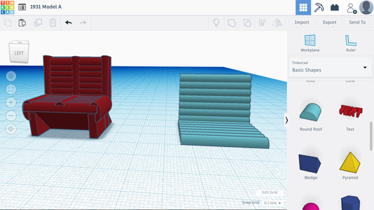


What's a nice car without a nice interior? For this part, we will be making the pedals, steering wheel, shifter, and seat. The first photo shows what the end product will look like.
We'll start by making the chair. If you search Model A you'll see a lot of cars with bench-style seats, so we're going to make one of those. The entire seat consists of only three types of pieces: squares, round roofs, and wedges. I will not be giving the dimensions of ever piece since there are over 20 shapes in the seat, so just try to mimic my design and worry about sizing after.
Start by taking a round roof and repeatedly copying and pasting it until you've placed 7 shapes for the base. Next, copy and paste all of the shapes you just made and tilt them up so that they resemble the back of the chair.
Now, add extra round roofs to the seat as a border. Place the border on the seat base and the back rest.
After adding the border to these areas, add an additional border to the sides and back. Stretch the round roof in the back so that it stretches across the entire length of the seat. Make the roof on the side larger than the border on top and pull it down.
After that, place a rectangle underneath the chair to be used as the legs. You'll also need two wedges to further form the legs. Place one in the front of the chair, rotate it so that the wedge side is facing in, and make it a hole. Place a wedge on the other side to make the chair more sturdy. Once you've done all of that, you can fuze everything together and place the chair inside of the car. You may need to make it smaller so that it fits properly.
Step 23: Part 7: Interior


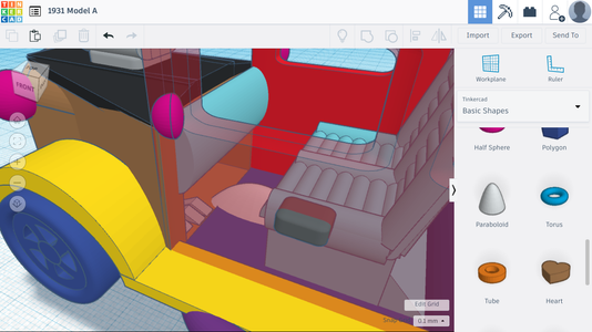
Now we need to put a space into the front of the car so that the driver has a place to put their feet. We also need to make a dashboard, pedals, and a shifter for the lever that we will include in the next step.
For the space in the front, take a rounded roof and a square hole and line them up with eachother. Use the hole to cut off half of the rounded roof. Use this piece to make the space by turning it into a hole, placing it towards the front of the interior, and fuzing it with the hood so that it makes the hole.
To make the dashboard, take one round roof and rotate it. Push it against the front of the car above the hole you just made. Make sure that it does not jut out too much since a real dashboard would allocate enough room for the driver.
To make the shifter, all you need to do is take the paraboloid, stretch it, and squish it down. Once you've done that, place it on the floor in the middle of the front half of the interior.
For the brake, accelerator, and clutch, take three triangular roofs from the selector, give them a variety of sizes, and line them up on the left side of the car underneath the dashboard.
Step 24: Part 7: Interior


Now we will make the steering wheel and lever for the shifter. To do this, we'll need to use the same concept that we used for making the wheels. If we take a large cylinderical hole and a small cylinder, we can have whatever we attach to the small cylinder spin in the real world. (Judges, this is not a project for Make It Move, it's for the Scene. The spin function is just a bonus.)
We'll make the steering wheel first. You'll need a torus, three cylinders, and a sphere. Set the radius of the torus to 3.5, the tube to 0.5, the sides to 24, and the steps to 24. You'll also need to set the dimensions to 11.98 x 11.98 x 1.37. Inside of the circle, make a skinny "X" with the cylinders. At the center, place a squished down sphere. And, on top of the sphere, place a cylinder with the dimensions 2.63 x 2.63 x 7.44.
Do not rotate the steering wheel until you complete this next part. Once you make the wheel, copy the cylinder. Make the second cylinder 2.9 x 2.9 x 7.20. Fuse all of the components on the steering wheel together (not including the cylinder you just made). Copy the steering wheel and put it to the side.
Now, bring the holed cylinder to the car, put the hole in the dashboard, and place the steering wheel in the hole. You may need to select the hood while putting the hole in, otherwise the hole might not go all the way through.
If you decide to print the model, make sure you prevent printing the wheel while it's inside the car. Instead, deselect it or remove it and print the steering wheel that you put to the side instead. Do the same for the car's wheels and shifter.
Step 25: Part 7: Interior

We'll repeat the same process for the lever. You'll need a cylinder and a sphere for this part.
Basically, all you need to do is put the sphere on top of the cylinder. Make sure the cylinder is a good fit for the shifter before putting the ball on, otherwise the ball might look stretched out if you need to minimize the part when it's already put together.
Like in the last part, you'll need to copy the cylinder. After copying it, make it about the new cylinder about 0.3 mm larger on the x and y axis (make it wider and longer, not taller). Move the hole to the center part, put a hole in it, and place the lever in.
Step 26: Part 7: Interior


Now for the last part of the interior. As I was looking through photos, I noticed that the dashboard would usually have a funny looking object on top of it. My guess is that it tells you how fast your going or how much gas you had left. So, I decided to make that too.
The entire part is made of cylinders. So, all you need to do is shorten them, stretch them, and configure them to look like the shape in the photo. After you've dome the first layer, place the speedometer and other parts (also cylinders) on top in the same pattern. I used 8 cylinders to make this piece.
Step 27: Part 8: Painting


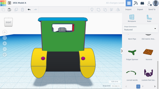
Congratulations! You've made a Model A completely from scratch! Now all that's left is coloring it to look like a real Model A. Also, if you're interested in making the scene to go with it, you can continue ahead. Otherwise, thank you for following this tutorial.
So, in order to paint the Model A, all you need to do is select the parts, go to colors in the part's settings, and clicking on one of the colors to use. You can also use the color wheel to make your own custom colors.
One other thing: you can select the transparent colors option to make certain object look clear or glassy. You may want to use this for the lights or mirrors.
One last thing: you may need to ungroup some shapes to color everything the right color. And, once you've finished coloring, you can fuze everything (minus the wheels, steering wheels, levers, etc.) together. If the model suddenly becomes one single color, just go to the color settings on the model and hit the multicolor option.
Step 28: Part 9: the Scene


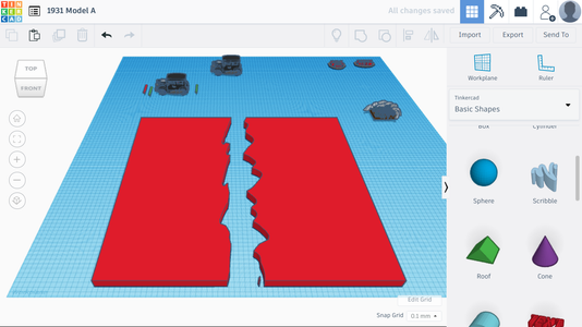

Once again, congratulations for completing the Model A. This next section will be entirely dedicated to making the scene. So without further ado, let's begin.
Start by taking a square from the selector. You are going to want to make it pretty big since there is a lot going on in this scene. You'll also want to use the scribble tool to make a large crack-like shape that will be used for the river.
Once you've made the crack, make the scribble into a hole and put it through the square. Since part of the scene is elevated, you'll need to make a copy of the scene. Once you've made the copy, use a shape to remove half of the scene. If you don't do this step, you'll not be able to properly elevate the scene.
Using the one side of the scene that you kept, place two or three more copies of it on top of one side to elevate it. Rotate the part on the top to make a more intense looking cliff.
You can also add the water into this step. Take another square, make it blue, make it transparent, and put it in the ravine. The hight of the shape controls how high the water is, so you can choose to either make it shallow or deep.
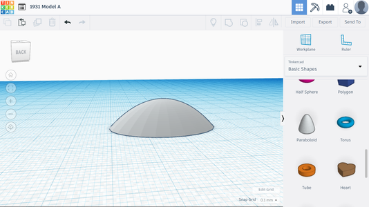
Step 29: Part 9: the Scene

Now that we have the main part of the scene, we can focus on the mountains. All that I had to do to make the mountains was take a parabola, set the number of steps to something low, like eight, and line up a bunch of them in random places with random sizes along the perimeter of the scene. I also set different mountains to have different steps, so one mountain had six steps while another had eight.
Do not cover the entire perimeter with mountains. It may be hard to take a good screenshot if you attempt to cover everything, so I reccomend only covering about half the scene.
Step 30: Part 9: the Scene


Now we can start adding trees, walls, and other aspects to our design. Before you start building, hit "W" to move the workplane and click onc of the spots on the scene's ground to lock it in place.
We'll need two types of shapes to make the evergreen trees: a cylinder and a cone. Place the cylinder on the workplane, make it smaller, increase the size of the cone, place the cone on top of the cylinder, and place two more cones on top of the first cone. Once you've made your tree, color it, fuze it together, and paste several trees onto the ground above and below the cliff.
You can add some variety to the trees by making them look bendy, by increasing the number of cones to make them look taller, inceasing the size of the cones, or by clumping groups more densely in some areas than in other areas.
We'll also add a stone wall to our scene. You can find the "BrickWall" on the first page of "All Shape Generators." You'll want the wall with the larger, rounder stones. Once you get that, line up a bunch of the stones in the scene, place some cylinders every so often along the wall, and add dips where the wall meets the edge of the cliff.
Step 31: Part 9: the Scene

We also need to make a camp site. To do this, we'll need a triangular roof, some spheres, and some rectangles.
To make the tent, place the roof down on the lower piece of ground. Hollow the triangle out using a smaller, holed verion of the triangle. You can also put a cylinder in the middle to make it look like its being held up.
To make the campfire, just use a bunch of spheres, make them different sizes and shapes, and place them in a circle.
Step 32: Part 9: the Scene


We're also going to add a waterfall. You'll need some spheres and the sribble tool for this part.
Use the scribble tool to make the waterfall by making a candycane-shaped design. Duplicate the design several times and place it on the side of the mountain. The water should cascade into the river, so add some white spheres to make it look like the water is frothy. Make the water in the waterfall a clear blue and matches the color in the river.
Step 33: Part 9: the Scene


Now it's time to add the cars. Make two copies of the Model A, bring them to the top of the cliff, and make one of them drive off. This scene depicts a police chase, where the criminal decides to make a risky move and swerves off the overhang (don't worry, he'll be alright). The police officer swerves to avoid going off along with him.
Once you've put the vehicles up on top, you can add tread marks using the scribble tool. Draw out designs on the gound that look like the cars had swerved at the top of the cliff, and make sure one of them leads directly to the edge.
Also, for the cop car, take off the fancy engine and exhaust pipes. Police cars in the '30s (and today) didn't have these, but they did have sirens!
Congratulations! You've completed this tutorial! I spent long hours designing and creating this Instructable, and I hope that it will inspire you to continue making fantastic things on Tinkercad! Happy building!

Participated in the
Tinkercad Student Design Contest


