

Introduction: How to Control DC Motors Rotation ?


Working on a autonomous robot, I needed to be able to control simultaneously two DC motors moves.
I already designed a system in july 2016 that runs rather well but I needed to improve speed measurement precision.
To do so I restarted from scratch and it was a good opportunity to publish this instructable.
Supplies
This system rely on:
- some mechanical components
- a simple electronic circuit
- some Arduino software tools.
All that is detailed further in this instructable.
Step 1: Working Principle

- a wheel with some holes is set on the rotation axis
- a LED provides an infrared light that goes thru holes each time LED is in front of a hole
- an infrared receiver provides an electrical signal that depends on the received light
- a microcontroler monitors the electical signal, counts the nomber of holes detected, compute the instantaneous speed and adjust the motor input voltage to fit with the expectations
This instructable demonstrates how to implement the system for only one motor.
Actually robots require more than one motor. That's why I developed software that can deal with up to four motors simultaneously. And that's also the reason I chose a microcontroler more powerfull than a UNO and I chose ATMega 2560
Step 2: Let's Start With the Electronic
Power supply
Motor need a dedicated power supply.
Power supply is delivered thru a motor controler (L298N in this case). For this model I chose a motor that needs a 12v power.
(if you need higher voltage take care to the motor driver specification for L298N you need to remove a jumper)
As I needed others 5v power supply for my robot, I do not use the Arduino 5v output to power the infrared LEDs.
As the robot runs on batteries I wanted to be able to power on/off the LEDs to save current. That's the job of the 2N222A transitor.
ATmega power supply is provided by the USB host connection
Step 3: Let's Start With the Electronic

Holes detection
Relies on the fact that a LED IR receiver (photodiode) resistance reduces when it receives light.
Before starting motor the LEDs are powered on.
The emitter current go thru a resistor to protect it.
The value of the resistor needs to be adjust depending on the LED characteritics and the distance between emitter and receiver.
The receiver current goes thru a resistor that will be used to detect voltage variations due to LED resistance variations.
A BC547 transistor is used to amplify the voltage changes to deliver to the Arduino.
The software monitors the voltage to detect holes.
Above in blue the signal before amplification, in red after amplification.
Notice that the signals widths (high and low) must be quite the same size (avoid too peaked signals). Those widths depends on the LED ligth and holes size.
Step 4: Electronic Schematic
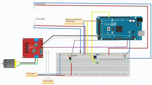


The schematic is available above as a fritzing file.
After you have done as the schematic, check manually that you get a good signal.
Take care the photodiode must be connected in reverse polarity
If having some oscilloscope it is useful to connect yellow and pink wire as above (orange wire later to be used as trigger)
Else you can use an arduino sketch and serial plotter to visualize the signals
Parts supply details
1 x ATmega2560 (you can find for less than 15$)
1 x breadboard (you can find 3 for 10$)
1 x LED IR emitter & 1 x LED IR receiver - (you can easely find both on the WEB (10$ for 50 of each))
1 x 2N222A transitor (less than 5$ for 100)
1 x BC547 transitor (less than 5$ for 100)
1 x L298N motor controller (you can get 5 for 15$)
2 x 220 ohms resistors
1 x 1k ohms resistor
1 x 10k ohms resistor
1 x 12v DC motor It can easily be found inside an old equipment (toy, printer...) or bought on the WEB for a few dollars
1 x 5v power supply
1 x 12v power supply
some wires
The wire between GPIO 3 and 7 is mandatory to get encoders interruptions
Motor is driven thru a L298N controler with 3 GPIOs (ENA (must be PWM), IN1 and IN2) to control rotation sens and torque
motor controller and motor can easily be replaced by other types
Attachments

Step 5: Let's Do the Mechanics


To develop and test the system I needed a mechanical prototype.
I did it with a 3d printer. The parts have been designed for an axis of 5mn diameter and a motor of 25mn of diameter.
- The bigest part has to be screwed on a wooden board.
- A little gear to be insert on the motor axis
- A big gear to be inserted on the main axis
- A coder wheel to be inserted on the main axis
- 2 rectangular bars for inserting the LEDs
Assemble as the above picture with some adding washers.
Obviously mechanics can be done differently
Step 6: Let's Do the Software

Some software principles
The 2 main libraries are
- the Arduino PID - you can find a lot of explanation on PID principle over the WEB
- WheelControl my encoders control library that you can download from Github
2 other libraries, I am used to use,and that can easily be replaced by your own code
- motorControl library that you can download from Github
- LookForString library that you can download from Github
The main code MotorControlExample code that you can download from Github
WheelControl library support up to 4 encoders running simultaneously
It works asynchronously versus the main code.
Each encoder is defined by the numbers of holes, the analog high and low thresholds and the analog GPIO Each encoder can be started indepently.
When some threholds (in term of holes number) are specified, the main code receives interrupts each time a threshold is reached.
Step 7: Some Details About the Example
There are 2 flags you can define before compiling
- debugOn will provide details during the run
- plotterOn will provide a graph showing how the actual speed fit with the target
10 commands to start and stop the motor, increase and decrease the speed and turns number requirement, change the sens rotation (clock, counterclock) and for braking or not at the end of the rotation
Notice that the system will retrun the turn overflow due to inertia unless you set brakOn - Braking is done by briefly reversing rotation
Step 8: Let's a First Try


By default the system will do 50 turns at 3.00 RPS and the encoder has 12 holes
Use serial input to enter commands
Enter 5 times s+ to increase the speed to 3.5 RPS (350/100)
Enter start and wait
At the end you will see on the serial link the total number of holes detected in this case 610
- 600 = 12*50 that are required
- 10 due to inertia overflow
In this case the effective speed was 3.45
Let's have a look at the oscillospe picture:
Step 9: Let's Have a Plotter Try

modify the code as below and upload it:
- //#define debugOn // uncomment to get details on the serial link
- #define plotterOn // uncomment to get graph on serial plotter (debugOn must be commented
open a Serial Plotter windows and enter start
the system is requested to run for 50 turns at 3.00 RPS
you will see a above how the PID control the wheel speed
Step 10: What Difference Brake on Does ?

Retry a run for 50 turns at 3.50 RPS and look at the end of the move
Now the overflow is reduce to one hole instead of 10 as you can see on the video and as shown on the oscilloscope picture
Step 11: Tunning


If it does not work well, uncomment #define debugOn and upload the sketch and enter start command
Firstly you have to check the good holes detection
reducing the requested turns number with the 't-' command will make the diagnostic easy
Look at the serial monitor. You will see something link below
18:05:55.515 -> 600 43min level:2 maxlevel: 865 50 500
"Timestamp -->" [nb of requested holes]" "[nb of detected holes]" min level:"[lowest analog input] " maxlevel:"[highest analog input]" "[low threshold]" "high threshold]
The first bold value is the holes number detected (43) and must increase regularly
The second bold value (2) is the lowest analog input value read since the start command. It must be much lower than 'incoderLowValue' (50 in this example)
The third bold value (865) is the highest analog input value read since the start command. It must be much higher than 'incoderHighValue' (500 in this example)
Notice that the difference between highest and lowest values must be big enough for the system to detect holes. If not you have to go back to the electronic schematic and eventually modify LEDs resistors.
IncoderLowValue and incoderHighValue can also be modified to fit with your electronic.
Now you know for sure that the system detect properly the holes,
Let's retry the plotter mode.
In case of speed instability, you may have to tune the PID to fit with your mechanical equipment.
You could find some good advices on the WEB on how to tune PID (Kp,Ki,Kd values).
2 more parameters must be taken into account:
minRPS: minimum rounds per second of your system that depends on the mechanical equipment (motor power, gears ratio, system inertia...). Under this value the system will be instable.
maxRPS: maximum rounds per second of your system that depends on the mechanical equipment (motor maximal power, gears ratio, system load...). The system can not run over this value. This parameter is used to by the wheelControl library to determine the timer interrupt frequency.
PID tuning can be facilitate with a graph by setting plotterOn annd debugPIDOn before compiling and using Serial Plotter (look at the graph above)
If you have an oscilloscope, you can check the good overflow detection. Connect the 'oscilloTrigger' GPIO and set a falling trigger.

Participated in the
Make it Move Contest 2020


![Tim's Mechanical Spider Leg [LU9685-20CU]](https://content.instructables.com/FFB/5R4I/LVKZ6G6R/FFB5R4ILVKZ6G6R.png?auto=webp&crop=1.2%3A1&frame=1&width=306)


