

Introduction: How to Make Your Own WIFI Gateway to Connect Your Arduino to IP Network ?


As so many people you think Arduino is a very good solution to do home automationand robotic !
But in term of communication Arduinos just come with serial links.
I am working on a robot that need to be permanently connected with a server that runs artificial intelligence code.
I tried to use RF network as I am used to do for domotic but it is not efficient enough. As the robot moves I can not use the Ethernet Arduino Shield. Arduino Wifi Shield are expensive and seems to me to be old design.
I needed something that can exchange data in a very simple and efficient way with a server.
That is why I decided to design a Gateway based on the very cheap and power efficient ESP8266 microcontroller.
Here you can find how to build the electronic component and download the software.
I used this gateway for Home automation and for Robotic.
This takes part of a global home automation infrastructure you can have a look here
I made another instructable that use a ESP8266 shield and avoid soldering
Supplies
Step 1: How Does It Work ?

The Gateway is based on an ESP8266 module.
This module is connected from one side with the serial link from the other side to IP network with the Wifi.
It acts as a black box. Data packets coming from the serial link are sent to an IP/Udp port and vis et versa.
You just have to set your own configuration (IP, WIFI ...) once the first time you will power on the Gateway.
It can transfer either raw ASCII and binary data (no HTTP, JSON...)
It is designed to connect objects with server home made softwares that need fast and frequent transfers of short packet of data.
It is easiest to use with Arduino Mega that have more than one UART (Arduino Mega for instance) but can run also with a UNO.
Step 2: What Are the Main Functions ?
Mostly it is a black box that convert and send serial data to UDP packet in both ways.
It has 3 LED that indicates the status and traffic of the Gateway.
It provides a GPIO that can be used by Arduino to wait for the Gateway to be WIFI and IP connected.
It runs in 3 different modes that are set with switchs:
- Gateway mode that is the normal mode
- Configuration mode used to set the parameters
- Debug mode that is for debuging mode
Most of the parameters can be modified to fit your needs.
Step 3: Build of Material

On top of your Arduino you will need
- 1 x ESP8266 module - I choose the MOD-WIFI-ESP8266-DEV from Olimex that costs around 5 euros that is quite easy to use.
- 1 x 5v power source
- 1 x 3.3v power regulator - I use LM1086
- 1 x 100 microfarad capacitor
- 1 x ULN2803 APG module (can be replace by 3 x transistors)
- 8 x resistors ( 3 x 1K, 1 x 2K, 1 x 2.7k, 1x 3.3K, 1x 27K, 1x 33k)
- 3 x LED (red, green, blue)
- 1 x Breadboard PCB
- some wires and connectors
During the building steps only, you will need
- 1 x FTDI 3.3v for the configuration
Soldering iron and tin
Before soldering it is important to setup all the components on breadboard and check everything is ok.
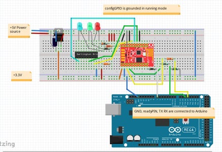
Step 4: Let's Start With the Electronic on the Breadboard !

The electronic layout is available in Fritzing format.
You can download it here the step 1:
https://github.com/cuillerj/Esp8266IPSerialGateway/blob/master/GatewayElectronicStep1.fzz
Just do as schema by taking care to the voltage.
Remember that ESP8266 does not support voltage higher than 3.3v.
The FTDI must be set to 3.3v.
Step 5: Let's Go to the Software !

Let's start with the Gateway side
I wrote the code with Arduino IDE. So you need ESP8266 to be known as board by the IDE.
Select the appropriate board with Tools / boards menu.
If you do not see any ESP266 in the list that means you may have to install ESP8266 Arduino Addon (you can find here the procedure).
All the code you need is available on GitHub. It is time to download it !
The main code of the Gateway is there: https://github.com/cuillerj/Esp8266IPSerialGateway...
On top of standard Arduino and ESP8266 includes the main code need these 2 includes:
LookFoString that is used to manipulate strings and is there: https://github.com/cuillerj/LookForString
ManageParamEeprom that is used to read and store parameters in Eeprom ans is there: https://github.com/cuillerj/ManageParamEeprom
Once you get all the code it's time to upload it into the ESP8266.
First connect the FTDI to an USB port of your computer.
I suggest you check the connection before trying to upload.
- Set the Arduino serial monitor to the new USB port.
- Set the speed to 115200 both cr nl (defaut speed for Olimex)
- Power on the breadboard (ESP8266 comes with software that deals with AT commands)
- Send "AT" with the serial tool.
- You must get "OK" in return.
If not check your connection and look at your ESP8266 specifications.
If you got "OK" your are ready to upload the code.
- Power off the breadboard, wait a few seconds,
- press on the black micro-swith of the ESP8266. It is normal to get some garbage on the serial monitor.
- Press on the upload IDE as for an Arduino.
- After the upload completed set serial speed to 38400.
You will see something as in the picture.
Congratulation you successfully uploaded the code !
Step 6: Let's Do the Configuration !

The configGPIO must be set to 1 for entering in configuation mode.
At first scan the WIFI by entering the command: ScanWifi. You will see a list of the detected network.
- Then set your SSID by entering "SSID1=yournetwork"
- Then set your password by enterind "PSW1=yourpassword"
- Then enter "SSID=1" to define the current network
- Enter "Restart" to connect the Gateway to your WIFI.
- You can verify you got an IP by entering "ShowWifi".
- The blue LED will be on and the red LED blinking.
It's time to define your IP server address by entering the 4 subaddresses (server that will run the Java test code). For instance:
- "IP1=192"
- "IP2=168"
- "IP3=1"
- "IP4=10"
The last required step is to set the UDP server listen port by entering "listenPort=xxxx".
Enter "ShowEeprom" to check what you just stored in Eeprom
Now plug the GPIO2 to ground to leave the configuration mode.
Your Gateway is ready to work !
There are some others commands you could find in the documentation.
Step 7: Let's Do the Arduino Side !

Firstly connect the Arduino.
If you have a Mega it will be easiest to start with. Nevertheless you can use a Uno.
To check your work the best is to use the example.
You can download it there: https://github.com/cuillerj/TestSerialLinkLibrary
It include SerialNetwork code that is here: https://github.com/cuillerj/SerialNetwork
Just upload the code inside your Arduino.
The green LED is blinking each time Arduino send data.
Step 8: Let's Do the Server Side !


The server example is a Java program that you can download here: https://github.com/cuillerj/ESP8266SerialUdpGatewa...
Just run it
Look at the Java console.
Look at the Arduino monitor.
Arduino send 2 different packets.
- The first one contains the digital pins 2 to 6 status.
- The second one contains 2 random values, the voltage level of A0 in mV and incremental count.
The Java program
- print the received data in hexadecimal format
- reply to the first kind of data with a random on/off value to set on/off the Arduino LED
- reply to the second kind of data with the received count and a random value.
Step 9: It Is Time to Do Some Soldering !


It works on the breadboard !
It is time to make it more robust by soldering parts on a PCB.
On top of what you did with the breadboard, you must add 3 connectors.
- C1 1 x pin one that will be use for entering in network trace mode.
- C2 3 x pins one that will be use to switch between running and configuration mode.
- C3 6 x pins one that will be used to connect the Gateway either to a Arduino or a FTDI.
C1 connected to GPIO2 has to be manually grounded if you want to activate the network traces.
C2 connected to GPIO 4 can be set in 2 different positions. One that set to ground for the normal running mode and one set to 3.3v for entering in configuration mode.
Set all the components on the PCB according to the diagram and afterward start to solder to get the final product !
Step 10: Let's Do the Final Test !

Start the Java test program.
Connect the Arduino.
Power on the Gateway .
And look at the Java console, the Arduino monitor, the Arduino LED and the Gateway LEDs.
Step 11: You Can Adapt This Design to Your Own Requirements !
Regarding the hardware
- If you choose some other ESP8266 you will have to adjust to the specifications.
- If you choose other 3.3v regulator it must deliver over 500mA and you will have to adapt the capacitor.
- You can modify the LED resistors to adjust the brightness.
- You can suppress all the LED but I recommend to keep at least the red on.
- You can replace the ULN2803 by 3 transistors (or less I you choose not to keep the 3 LED).
- I did test but there it must work with 3.3v Arduino boards. Just connect Tx Rx to the 3.3v connector.
Regarding configuration
- You can store 2 different SSID and switch
- You can modify the GPIO used
Regarding the software
- You can do whatever you want but please let me know if you find some improvements.

![Tim's Mechanical Spider Leg [LU9685-20CU]](https://content.instructables.com/FFB/5R4I/LVKZ6G6R/FFB5R4ILVKZ6G6R.png?auto=webp&crop=1.2%3A1&frame=1&width=306)


