

Introduction: Marblevator, Floating Tracks.


After creating "Marblevator, Tracks", family and friends suggested I hide the mechanism from the front view. So after much thought and more than a few trial and error attempts, "Marblevator, Floating Tracks" is finally finished!
The model utilizes magnetics (sixteen 6mm diameter by 2mm thick), brass axles (sixteen 12mm long by 1.85mm diameter) and ball bearings (sixteen 2mm thick by 5mm diameter by 2.5 mm diameter center hole) in order to achieve a "floating illusion" while using little power (approximately 20ma).
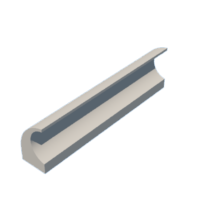
The model operates by raising and lowering two slides via a modified scotch yoke mechanism, the two slides being guided using sliding dovetails. Each slide contains magnets and rides on miniature ball bearings, the ball bearings being used to minimize friction. The two tracks also contain magnets and ride on miniature ball bearings as well. The design result is such that with the tracks magnetically coupled to the slides, they follow the slides as they are raised and lowered with no obvious mechanical connection when viewed from the front of the model, thus the tracks appear to "float" up and down the flat surface of the guides.
As usual, I probably forgot a file or two or who knows what else, so if you have any questions, please do not hesitate to ask as I do make plenty of mistakes.
Designed using Autodesk Fusion 360, sliced using Ultimaker Cura 4.12.1, and 3D printed in PLA on Ultimaker S5s and an Ultimaker 3e.
Supplies
Soldering iron and solder.
AWG 22 red and black stranded wire.
Thick cyanoacrylate glue.
Step 1:
I acquired the following parts:
- One 100rpm 6vdc n20 gear motor.
- One "1.8v 3v 5v 6v 7.2v 12v 2A 30W low voltage DC motor speed controller PWM 1803BK adjustable drive switch with speed control knob".
- One four AAA cell switched battery pack.
- One 12mm plastic marble.
- One 12" by.072" (1.83mm) brass rod.
- Sixteen 2mm by 5mm by 2.5mm ball bearings.
- Sixteen 6mm by 2mm neodymium disk magnets.
I 3D printed the following parts at .15mm layer height, 20% infill and no supports:
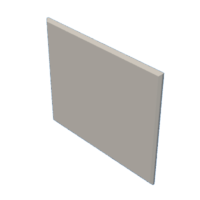
- One "Base.stl".
- Three "Bolt (M8 by 1.25 by 19mm).stl".
- Two "Gear Axle.stl".
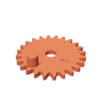
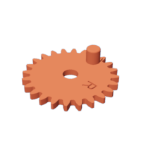
- One "Gear Left.stl".
- One "Gear Motor.stl".
- One "Gear Plate Spacer.stl".
- One "Gear Plate.stl".
- One "Gear Right.stl".
- One "Guides.stl".
- Two "Slide.stl".
- One "Track Left.3mf".
- One "Track Right.3mf".
Note the files with a ".3mf" extension are dual extrusion parts, however I've also include the individual files required if you wish to print them separately and assembly them.
This is a high precision 3D print and assembly model using at times very small precision parts in very tight spaces. Prior to assembly, test fit and trim, file, sand, polish, etc. all parts as necessary for smooth movement of moving surfaces, and tight fit for non moving surfaces. Depending on you printer, your printer settings and the colors you chose, more or less trimming, filing, sanding and/or polishing may be required. Carefully file all edges that contacted the build plate to make absolutely certain that all build plate "ooze" is removed and that all edges are smooth. I used small jewelers files and plenty of patience to perform this step.
The model also uses threaded assembly thus an M8 by 1.25 tap and die will assist with thread cleaning if necessary.
Attachments
 Base.stl
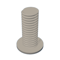
- Bolt (M8 by 1.25 by 19mm).stl
- Gate.stl
- Gear Axle.stl
- Gear Left.stl
- Gear Motor.stl
- Gear Plate Spacer.stl
- Gear Plate.stl
- Gear Right.stl
- Guides.stl
- Slide.stl
- Track Left Joiner.stl
- Track Left Lower.stl
- Track Left Upper.stl
- Track Left.3mf
- Track Right Joiner.stl
- Track Right Lower.stl
- Track Right Upper.stl
- Track Right.3mf


Step 2: Assemble the Slides.


To assemble the slides, I performed the following steps:
- Cut 16 12mm in length bearing axles from the brass rod.
- Positioned one 2mm by 5mm by 2.5mm in a bearing socket in "Slide.stl".
- Pressed one of the bearing axles into the hole in the slide, through the bearing and into the slide axle pocket.
- Secured the axle in position with a small dot of glue.
- Repeated the previous three steps for the three remaining bearings and axles for this slide assembly.
- Placed a small dot of glue in each of the four magnet pockets in the slide assembly.
- Pressed one 6mm by 2mm disk magnet into each of the four the magnet pockets making certain all the polarities matched and that the magnets were flush with the slide surface.
- Repeated the previous six steps for the remaining slide.
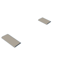
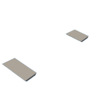
Step 3: Assemble the Tracks.


To assemble the tracks, I performed the following steps:
- As in the slide assembly, positioned four ball bearings in "Track Right.3mf" and secured each in place with a bearing axle and a small dot of glue.
- As in the slide assembly, applied small dots of glue into each track magnet pocket then pressed one 6mm by 2mm disk magnet into each of the four magnet pockets, making certain these magnets matched the polarity of the slide assembly (I took more than a few moments to examine the final orientation of the slide and track assemblies in the guide prior to gluing the magnets in place, pay very careful attention to this step).
- Repeated the previous steps with the left track.
Step 4: Assemble the Gear Plate.


To assemble the gear plate, I performed the following steps:
- Soldered 80mm long red and black wires to the gear motor "+" and "-" terminals.
- Pressed the gear motor into "Gear Plate.stl".
- Attached "Gear Right.stl" to the gear plate assembly using one "Gear Axle.stl".
- Attached "Gear Left.stl" to the gear plate assembly using the remaining "Gear Axle.stl".
- Made certain both gears rotated with ease.
- With the "R" on the right gear upwards and the "L" on the left gear upwards, pressed "Gear Motor.stl" onto the motor shaft and adjusted such that the motor gear surfaces aligned with the right and left gears.
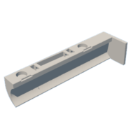
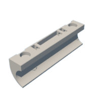
Step 5: Assemble the Guide Plate.


To assemble the guide plate, I performed the following steps:
- Slid the right and left slide assemblies into "Guide.stl" carefully noting the orientation of each and making certain each assembly slid in the guide with ease.
- Positioned "Gear Plate Spacer.stl" over the three holes in the guide plate.
- Aligned the gear plate assembly with the slide assemblies such that the pins on the right and left gears fit into the slots in the right and left slide assemblies, then secured the gear plate assembly in place using three "Bolt (M8 by 1.25 by 19mm).stl".
- Pressed "Gate.stl" into the slot in the guide.
- Positioned the guide plate assembly over "Base.stl", pressed into position, then secured in place with small dots of glue.
- Magnetically attached the right track assembly to the guide assembly.
- Magnetically attached the left track assembly to the guide assembly.
Step 6: Final Assembly.


For final assembly, I performed the following steps:
- Attached the battery pack wires to the motor speed controller "Power" pins, red to "+" and black to "-".
- Attached the motor wires to the motor speed controller "Motor" pins, red to "+" and black to "-".
With assembly complete, I turned on the battery pack and motor speed controller, placed the 12mm plastic marble on the track, then carefully adjusted the speed controller to attain the desired operation. Note the marbles I purchased vary in size and weight, so careful selection may be necessary to attain the desired operation.
And that is how I 3D printed and assembled "Marblevator, Floating Tracks".
I hope you enjoyed it!


