

Introduction: Marblevator, Golf


I always looked forward to the time my father and I spent on the golf course when I was much, much younger. So this model, "Marblevator, Golf", is an animatronic design combining 3D printing, electronics and software in order to whimsically imitate our golf outings of years ago, while at the same time simulating our sons and grandsons golf outings today.
As usual, I probably forgot a file or two or who knows what else, so if you have any questions, please do not hesitate to ask as I do make plenty of mistakes.
Designed using Autodesk Fusion 360, sliced using Ultimaker Cura 4.12.1 Engineering profile, and 3D printed in PLA and TPU on Ultimaker S5s.
Supplies
- Soldering iron and solder.
- Thick cyanoacrylate glue.
- AWG 28 stranded wire.
- 2mm heat shrink tubing.
- Double sided servo tape.
Step 1: Parts.
I acquired the following parts:
- One Arduino Nano 33 ioT with two header pin blocks.
- Two 12 pin socket blocks.
- One 500ma USB power supply.
- One USB to Micro USB cable.
- One prototype board (Adafruit Perma-Proto 1/2 Sized Breadboard).
- Six miniature servos (smraza S51 9g).
- Two 470mfd 25vdc electrolytic capacitors.
- One 16mm by 2mm diameter steel pin.
- One 85mm by 1.5mm diameter brass rod.
- One 6mm ball bearing.
- Eight 3mm diameter by 1mm thick neodymium magnets.
I've include the file "Parts.pdf" describing how I 3D printed the parts for this model.
This is an extremely high precision 3D print and assembly model using at times very small precision 3D printed parts in very tight spaces. Prior to assembly, test fit and trim, file, sand, etc. all parts as necessary for smooth movement of moving surfaces, and tight fit for non moving surfaces. Depending on you printer, your printer settings and the colors you chose, more or less trimming, filing and/or sanding may be required. Carefully file all edges that contacted the build plate to make absolutely certain that all build plate "ooze" is removed and that all edges are smooth. I used small jewelers files and plenty of patience to perform this step.
The model also uses threaded assembly thus an M8 by 1.25 tap and die will assist with thread cleaning if necessary.
Attachments
 Parts.pdf
- Arms.stl
- Axle, Frames.stl
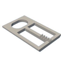
- Base.stl
- Axle, Servos.stl
- Bolt (8M by 1.25 by 5).stl
- Bolt (8M by 1.25 by 10).stl
- Cam, Hip.stl
- Cam, Lift.stl
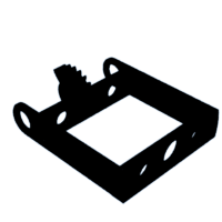
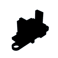
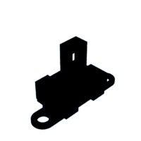
- Enclosure.stl
- Flag.3mf
- Frame, Legs.stl
- Frame, Shoulder, Bushing.stl
- Frame, Shoulder.stl
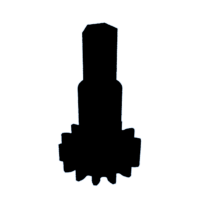
- Gear (1m, 14t).stl
- Gear, Head (1m, 14t).stl
- Green.stl
- Head, Face.stl
- Head.stl
- Junior, Arm, Left.stl
- Junior, Head, Face.stl
- Junior, Head.stl
- Junior, Legs.stl
- Junior, Lever, Arm, Left.stl
- Junior, Axle, Head.stl
- Junior, Servo, Mount.stl
- Junior, Spline, Lever, Arm, Left.stl
- Junior, Torso.stl
- Legs.stl
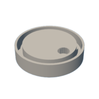
- Lift.stl
- Putter, Offset.3mf
- Rack.stl
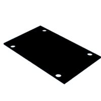
- Return.stl
- Servo, Mount.stl
- Shoulder.stl
- Spline.stl
- Torso Cover.stl
- Torso.stl


Step 2: Wiring.


For the model wiring, I performed the following steps:
- Cut the prototyping board leaving only pins 1 through 15.
- Soldered the VUSB shorting pads on the bottom of the Nano 33 ioT.
- Soldered the header pin blocks to the Nano 33 ioT.
- Pressed two 12 pin socket blocks onto the header pins as shown.
- Positioned the Nano 33 ioT on the prototyping board as shown, then soldered the socket blocks to the prototyping board.
- Soldered a wire between the Nano 33 ioT ground pin and the ground bus on the prototyping board.
- Soldered a wire between the Nano 33 ioT VUSB pin and the positive bus on the prototyping board.
- Soldered a red and black wire between the two buses on the prototyping board.
- Soldered two 470mfd electrolytic capacitors, one each on each power bus, as shown.
- Soldered three 6 pin header pin blocks onto the prototyping, the first block aligned with the Nano 33 ioT pins D6 through D11, and the remaining two on the ground and power bus adjacent to the first block.
- Removed the plastic connector shell from each of the servos (as an option, I cut off the connectors and soldered a connector pin to each wire).
- Insulated each connector pin with heat shrink tubing.
Step 3: Software.
I've included the Arduino sketch "Marblevator_Golf_Sketch.ino". The sketch is designed to operate in two modes, servo home and normal.
For servo setup, set the constant "SERVO_HOME" to "1", then compile and download the sketch to the Nano 33 ioT. In this mode, the servos are set to their home position for assembly and alignment purposes.
For normal operation, set the constant "SERVO_HOME" to "0", then compile and download the sketch to the Nano 33 ioT. In this mode, the animation runs in an endless loop.
Attachments
Step 4: Lift and Senior Servo Mount Assembly.


To assemble the lift and senior servo mount, I performed the following steps:
- After homing the lift servo, attached "Cam, Lift.stl" to the servo such that the cam was at its lowest position, then secured in place with a servo arm screw.
- Pressed the 16mm by 2mm diameter pin into "Lift.stl".
- Slid the pin into the cam slot, slid the servo and lift into the servo mount and lift hole on "Base.stl", then secured the servo to the base using two servo screws.
- After homing the senior head and torso servos, pressed one "Spline.stl" onto each servo such that two points of the spline hexagonal holes were aligned front to back.
- Mounted both servos onto "Servo, Mount.stl" using two servo screws each.
- After homing the senior hip servo, attached "Cam, Hip.stl" to the servo such that the index line on the cam pointed straight down, then secured in place with a servo arm screw.
- Mounted the servo mount assembly to the base using two "Bolt (8M by 1.25 by 10).stl".
Step 5: Junior Servo Mount Assembly.


To assemble the junior servo mount, I performed the following steps:
- After homing the junior head servo, I pressed the remaining spline onto the servo such that two points of the spline hexagonal hole were aligned front to back.
- Mounted the servo onto "Junior, Servo, Mount.stl" using two servo screws.
- Bent 3mm of each end of the 85mm by 1.5mm brass wire down 90 degrees, slid "Junior, Lever, Arm, Left.stl" onto one end as shown, slid "Junior, Spline, Lever, Arm, Left.stl" onto the other end as shown, then secured both into position on the wire with a final 1mm bend on each end.
- After homing the junior arm servo, I pressed the spline onto the servo such that the spline arm was straight down, then secured in place with a servo arm screw.
- Attached the junior servo mount assembly to the base assembly using two 8M by 1.25mm by 10 bolts.
Step 6: Base Assembly.


To assemble the base, I performed the following steps:
- Secured the protoboard assembly into the base assembly with double sided tape such that the USB connector faced toward the front of the base assembly.
- Attached the servo signal pins to the protoboard starting with the senior head servo on D6, followed by the senior hip on D7, lift on D8, senior shoulder on D9, junior arm on D10 and junior head on D11, with each servo power and ground pins on the power and ground pins adjacent to the signal pin.
- Slid "Rack.stl" into "Legs.stl" as shown.
- Positioned the rack slot over the hip servo cam, then slid the legs down pressing them into the leg slots in the senior servo mount assembly.
- Attached "Return.stl" to the base assembly using four 8M by 1.25 by 10mm bolts.
- Slid "Green.stl" onto the base assembly.
- Pressed one "Gear (1m, 14t).stl" onto the longer hexagonal end of "Axle, Servos.stl" (this is the shoulder axle).
- Pressed the remaining 1mm 14t gear upside down onto the longer hexagonal end of the remaining servo axle (this is the head axle).
- Positioned the shoulder axle assembly into "Frame, Shoulder.stl" as shown.
- Positioned the head axle assembly into the shoulder frame assembly as shown.
- Slid the shoulder frame assembly onto the leg frame, aligning the gear index marks straight forward, pressed the axles into the splines, then made sure the gear teeth on the leg frame aligned with the gear teeth on the rack such that the shoulder frame was vertical.
- Slid "Torso.stl" onto the shoulder frame, then secured the torso and shoulder frame in place with two "Axle, Frames.stl".
- Inserted "Gear, Head (1m, 14t).stl" into the shoulder frame with the gear index mark facing straight forward.
- Glued "Head, Face.stl" onto "Head.stl".
- While holding the head gear in position, slid "Shoulder.stl" onto the shoulder frame such that the index mark faced forward, the gear engaged with the shoulder gear and the shoulder leading edge was parallel with the torso, secured it in place with "Frame, Shoulder, Bushing.stl", then pressed the head assembly onto the head gear.
- Pressed "Junior, Legs.stl" onto the base assembly.
- Slid the junior lever arm left into "Junior, Torso.stl" such that the left arm lever faced to the rear of the torso, slid the arm into the shoulder socket hole in the torso, slid the torso onto the legs, then secured the torso to the legs using two "Bolt, (8M by 1.25 by 5).stl".
- Pressed "Junior, Arm, Left.stl" onto the left arm lever hexagonal shaft.
- Glued "Junior, Head, Face.stl" onto "Junior, Head.stl".
- Pressed "Junior, Axle, Head.stl" into the head assembly.
- Slid the head axle through the torso then pressed it into the junior head servo spline.
- Pressed "Flag.3mf" into the hand of junior arm such that the bottom of the flag staff was level with the green.
- Pressed "Putter, Offset.3mf" into "Arms.stl".
- Glued the arm assembly to senior shoulder.
- Pressed four magnets each into senior torso and "Torso, Cover.stl", then attached the cover to the torso.
Step 7: Final Assembly.


Prior to final assembly, I set the sketch constant "SERVO_HOME" to "0", then compiled and downloaded the sketch to the Nano 33 ioT. Next I adjusted the sketch initial positions and limits for proper animation as well as the physical positions of the putter and flag. With the animation operating as I desired, I performed the final assembly steps:
- Routed the USB cable into the hole in "Enclosure.stl", around the outside of the base, and into the Nano 33 ioT usb connector.
- Slid the enclosure onto the assembly then secured in place using eight 8M by 1.25 by 10 bolts.
- Glued "Legs.stl" to the front of senior leg frame with small two dots of glue.
And that is how I 3D printed, wired, assembled and programmed "Marblevator, Golf".
I hope you enjoyed it!

Judges Prize in the
Microcontroller Contest


