

Introduction: Marblevator, Pick and Place, Version 3


"Marblevator, Pick and Place, Version 3" is my third "pick and place mechanism" based Marblevator. The model uses a 3D printed TPU gripper to lift a ball bearing between the end of the track to the start of the track. The mechanism that generates the required movement of the gripper from the end of the track to the start of the track differs from my version 2 mechanism resulting in a reduced part count.
As usual, I probably forgot a file or two or who knows what else, so if you have any questions, please do not hesitate to ask as I do make plenty of mistakes.
Designed using Autodesk Fusion 360, sliced using Cura 4.12.1, and 3D printed in PLA on Ultimaker S5s.
Supplies
- Soldering iron and solder.
- Thick cyaonacrylate glue.
- Double sided tape.
Step 1: Parts.
I acquired the following parts:
- One dual AAA cell switched battery pack.
- Two AAA cells.
- One N20 50RPM 6VDC gear motor.
- One 11mm ball bearing.
- Four rubber stick on pads.
Unless noted otherwise, I 3D printed the following parts in PLA at .15mm layer height, 20% infill:
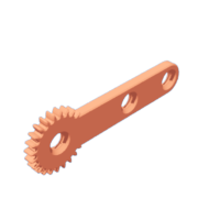
- One "Arm.stl".
- Three "Axle, Gears.stl".
- One "Base, Gear (1m, 48t).stl".
- Four "Bolt (M8 by 1.25 by 14mm).stl".
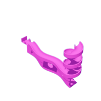
- One "Eccentric.stl".
- One "Gear (1m, 24t), Gripper.stl".
- One "Gear (1m, 24t).stl".
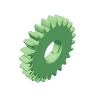
- One "Gear (1m, 48t).stl".
- One "Gear, Motor (1m, 24t).stl".
- One "Gripper.stl", TPU.
- One "Plate, Eccentric.stl".
- One "Rack.stl".
- Two "Spacer, Track.stl".
- One "Track, Joiner.stl".
- One "Track, Start.stl", .06mm layer height.
- One "Track.stl", .1mm layer height.
This is a high precision print and assembly model using at times very small parts and in very tight spaces. Prior to assembly, test fit and trim, file, sand, etc. all parts as necessary for smooth movement of moving surfaces, and tight fit for non moving surfaces. Depending on you printer, your printer settings and the colors you chose, more or less trimming, filing and/or sanding may be required. Carefully file all edges that contacted the build plate to make absolutely certain that all build plate "ooze" is removed and that all edges are smooth. I used small jewelers files and plenty of patience to perform this step.
The model also uses threaded assembly thus an M8 by 1.25 tap and die will assist with thread cleaning if necessary.
Attachments
 Arm.stl
- Axle, Gears.stl
- Base, Gear (1m, 48t).stl
- Bolt (M8 by 1.25 by 14mm).stl
- Eccentric.stl
- Gear (1m, 24t), Gripper.stl
- Gear (1m, 24t).stl
- Gear (1m, 48t).stl
- Gear, Motor (1m, 24t).stl
- Plate, Eccentric.stl
- Gripper.stl
- Gripper, PLA.stl
- Gripper, TPU.stl
- Rack.stl
- Spacer, Track.stl
- Track, Joiner.stl
- Track, Start.stl
- Track.stl


Step 2: Assemble the Eccentric Plate.


To assemble the eccentric plate, I performed the following steps:
- Inserted two AAA batteries into the switched battery pack, then soldered the battery pack wires to the motor such that the motor shaft rotated counter clockwise when viewed from the motor shaft end of the motor.
- Placed two of the rubber stick on pads on the bottom of "Plate, Eccentric.stl".
- Pressed the motor into the eccentric plate assembly.
- Attached "Gear (1m, 48t).stl" to the base assembly using "Eccentric.stl", making certain the gear rotated with ease.
- Pressed "Gear, Motor (1m, 24t).stl" onto the motor shaft.
Step 3: Assemble the Arm and Base Gear.


To assemble the arm and base gear, I performed the following steps:
- Attached "Gear (1m, 24t), Gripper.stl" to "Arm.stl" using one "Axle, Gears.stl", making certain the gear rotated with ease.
- Pressed "Gripper.stl" onto the gripper gear in the orientation shown.
- Slid "Rack.stl" onto "Base, Gear (1m, 48t).stl" making certain the rack slid with ease on the base.
- With the rack flush with the top of the base slides, attached the arm assembly to the base such that it was horizontal using one "Axle, Gears.stl".
- With the rack at the top of the base slides, the arm horizontal and the gripper pointing straight down, attached "Gear (1m, 24t).stl" to the arm using one "Axle, Gears.stl".
- Made certain the mechanism operated with ease.
Step 4: Final Assembly and Alignment.


For final assembly, I performed the following steps:
- Positioned the plate assembly behind the base assembly.
- Glued "Track, Start.stl" to "Track, Joiner.stl".
- Positioned the two "Spacer, Track.stl" over the upper holes of the base assembly.
- Secured the track start and joiner assembly to the base and plate assemblies using two "Bolt (M8 by 1.25 by 14mm).stl".
- Positioned "Track.stl" over the assembly and secured in place with two "Bolt *(M8 by 1.25 by 14mm).stl".
- Placed two of the rubber stick on pads on the bottom of the track.
- Applied double sided tape to the rear of the battery case then secured it to the assembly.
With assembly complete I placed the ball bearing at the end of the track and powered up the model. If the arm failed to pick up the ball bearing at the end of the track, I loosend the bolts securing the track to the base, lifted the track, then tightened the bolts. If the arm failed to release the ball bearing at the start of the track, I loosend the bolts securing the track start and joiner to the base, slid the track start and joiner left, then tightened the bolts. With the alignment complete, you may wish to glue the joiner and track sections together.
And that is how I 3D printed, assembled and aligned "Marblevator Pick and Place, Version 3".
I hope you enjoyed it!


