

Introduction: Marblevator Pick and Place, Version 4.


"Marblevator Pick and Place, Version 4" is my fourth pick and place based Marblevator. This model utilizes four 3D printed TPU "fingers" to pick up a marble from the end of the track and place it at the start of the track. The fingers are mounted to a gear which rotates 270 degrees in order to pick up the marble at the end of the track then lift it and place it at the start of the track.
As usual, I probably forgot a file or two or who knows what else, so if you have any questions, please do not hesitate to ask as I do make plenty of mistakes.
Designed using Autodesk Fusion 360, sliced using Ultimaker Cura 4.12.1 Engineering profile, and 3D printed in PLA and TPU on Ultimaker S5s.
Supplies
Soldering Iron and Solder.
Thick cyanoacrylate glue.
Step 1: Parts.
I acquired the following parts:
- One N20 45RPM 6VDC gear motor.
- One four AA cell switched battery pack with wires.
- Four AA cell batteries.
- Four 14mm plastic marbles.
I 3D printed the following parts in PLA at .15mm layer height, 20% infill with no supports unless otherwise noted:
- One "Axle, Gear, Drive.stl".
- One "Axle, Gear.stl".
- One "Base.stl".
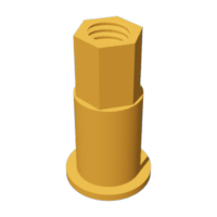
- Five "Bolt (M8 by 1.25 by 8MM).stl".
- One "Bolt, Axle, Gear, Drive.stl".
- One "Cam.stl".
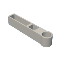
- One "Carriage.stl".
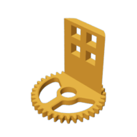
- One "Gear (1m 36t).stl".
- One "Gear, Drive (1m 36t).stl".
- Four "Gripper.stl", .1mm layer height, TPU.
- Four "Guide.stl".
- One "Pin, Rack.stl".
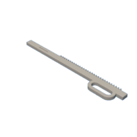
- One "Rack.stl".
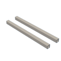
- Two "Rail.stl".
- One "Top.stl".
- One "Tower, Motor.stl".
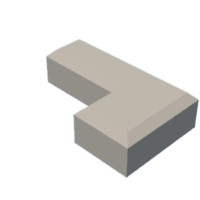
- One "Track Stiffeners.stl".
- One "Track Stop.stl".
- One "Track.stl", .06mm layer height.
This is a high precision 3D print and assembly model using at times very small precision 3D printed parts in very tight spaces. Prior to assembly, test fit and trim, file, sand, etc. all parts as necessary for smooth movement of moving surfaces, and tight fit for non moving surfaces. Depending on you printer, your printer settings and the colors you chose, more or less trimming, filing and/or sanding may be required. Carefully file all edges that contacted the build plate to make absolutely certain that all build plate "ooze" is removed and that all edges are smooth. I used small jewelers files and plenty of patience to perform this step.
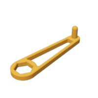
The model also uses threaded assembly thus an M8 by 1.25 tap and die will assist with thread cleaning if necessary.
Attachments


Step 2: Track Assembly.


To assemble the track, I performed the following steps:
- Glued the two "Track Stiffeners.stl" to "Track.stl" such that the flat ends were flush with the bottom of the track and the beveled ends were parallel with the top of the track (the stiffeners are different lengths, the left one in the image is shorter than the right one).
- Glued "Track Stop.stl" to the end of the track assembly, centered in the track end marble well.
- Glued "Base.stl" to the track assembly aligning the two as shown in the image.
Step 3: Carriage Assembly.


To assemble the carriage, I performed the following steps:
- Secured two "Guide.stl" to one end of "Carriage.stl" using two "Bolt (M8 by 1.25 by 8MM).stl".
- Repeated the previous step for the remaining end of the carriage assembly.
- Slid the two "Rail.stl" into the carriage assembly guides to make certain the rails slid inside the guides with ease and adjusted the guide rotation as required for smooth operation.
- Glued four "Gripper.stl" into the four holes in "Gear (1m 36t).stl" making certain the cups in each opposing gripper faced towards each other.
- Secured the gripper and gear assembly to the carriage assembly using one "Axle, Gear.stl" making certain the gear rotated with ease on the axle.
Step 4: Base Assembly.


To assemble the base, I performed the following steps:
- Pressed two "Rail.stl" into the hexagonal holes in "Base.stl".
- Secured "Pin, Rack.stl" onto "Rack.stl" using one "Bolt (M8 by 1.25 by 8MM).stl".
- Pressed the rail assembly into the base assembly.
- Slid the carriage assembly onto the rails and slid the assembly fully downward, making certain the assembly moved with ease.
- Pressed "Top.stl" onto the base assembly.
Step 5: Final Assembly.


For final assembly, I performed the following steps:
- Inserted four AA batteries into the battery case and turned the switch off.
- Soldered the battery case wires to the gear motor.
- Slid "Axle, Gear, Drive.stl" into "Tower, Motor.stl".
- Pressed "Gear, Drive (1m 36t).stl" onto the axle.
- Pressed "Cam.stl" onto the axle.
- Secured the cam and gear to the axle using "Bolt, Axle, Gear, Drive.stl" making certain the cam, gear and axle rotated with ease.
- Pressed the motor into the motor tower assembly.
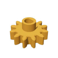
- Pressed "Gear, Motor (1m, 12t).stl" onto the motor shaft.
- With the cam pin in the carriage slot, pressed the motor tower assembly onto the base.
With assembly complete, I placed one marble into the track end marble well and turned on the battery pack, then carefully adjusted the rack pin position so that the marble was removed from the gripper with ease.
And that is how I 3D printed and assembled "Marblevator Pick and Place, Version 4".
I hope you enjoyed it!


