

Introduction: Marblevator, Wheels, Vertical


After publishing "Marblevator, Wheels", YouTube follower RobotHut (https://www.youtube.com/user/Robothut) commented regarding the use of "cones" in the wheels as opposed to "cylinders". By using cones, he explained, the model could remain vertical during operation as opposed to being tilted rearward, and the cone shape would provide the slope necessary to transfer the ball bearing from the front wheel, to the rear wheel, then to the base.
So here it is, "Marblevator, Wheels, Vertical" standing vertical and using cones in the wheels as opposed to cylinders. In the linked three part video, the cad model, assembly process and operation are shown.
Designed using Autodesk Fusion 360, sliced using Ultimaker Cura 4.1, and 3D printed in PLA on Ultimaker S5s.
Supplies
Thick cyanoacrylate glue.
Step 1: Parts.

I acquired an 8mm ball bearing from a local hardware store, then I 3D printed one each of all parts at .16mm layer height with 20% infill and no supports
Prior to assembly, I test fitted and trimmed, filed, drilled, sanded, etc. all parts as necessary for smooth movement of moving surfaces, and tight fit for non moving surfaces. Depending on your slicer, printer, printer settings and the colors you chose, more or less trimming, filing, drilling and/or sanding may be required to successfully recreate this model. I carefully filed all edges that contacted the build plate to make absolutely certain that all build plate "ooze" is removed and that all edges are smooth using small jewelers files and plenty of patience.
The model uses threaded assembly, so I used an 8mm by 1.25 tap and die for thread cleaning.
Attachments


Step 2: Assembly.


To assemble the model, I performed the following steps:
- Threaded "Knob.stl" into "Crank, Gear, Upper.stl".
- Inserted "Wheel, Upper.stl" into position in "Base.stl".
- Pressed "Gear, Upper (1.5m, 20t).stl" onto the upper wheel hexagonal shaft and rotated the upper wheel and gear such that the dot pointed straight down.
- Threaded the crank assembly into the upper wheel.
- Inserted "Wheel, Lower.stl" into position in the base assembly.
- Rotated the lower wheel such that the hexagonal shaft flat was horizontal, then pressed "Gear, Lower (1.5m, 20t).stl" onto the lower wheel hexagonal shaft such that the dot pointed straight up aligning with the dot in the upper gear.
- Threaded "Bolt, Gear, Lower.stl" into the lower gear.
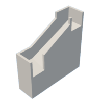
- Applied small dots of thick cyanoacrylate glue to the face of the base assembly.
- Pressed "Base, Front.stl" onto the base assembly and held the assembly together until the glue set.
And that is how I 3D printed and assembled "Marblevator, Wheels, Vertical". I hope you enjoyed it!


