

Introduction: Rack and Pinion, 3 to 1 Stroke.


"Rack and Pinion, 3 to 1 Stroke" is a mechanism I designed for an upcoming automaton. The mechanism is designed to increase the stroke of a modified Scotch Yoke mechanism by a factor of 3 to 1 in order to provide a large (68mm) stroke from a short (68 / 3 = 22.67mm) stroke.
Designed using Autodesk Fusion 360, sliced using Ultimaker Cura 4.12.1, and 3D printed in PLA on Ultimaker S5s and an Ultimaker 3 Extended.
Supplies
- AWG28 wire.
- Solder.
- Soldering Iron.
- Thick cyanoacrylate glue.
Step 1: Parts.
I acquired the following parts:
- One 6VDC 30RPM N20 gear motor.
- One 4.5VDC power supply.
- One coaxial connector compatible with the power supply.
I 3D printed the following parts at .15mm layer height, 20% infill, no supports:
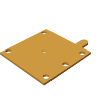
- One "Base.stl".
- Four "Bolt (M8 by 1.25, 6mm).stl".
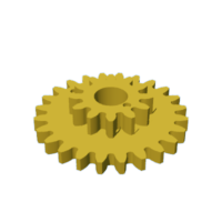
- One "Gear, Compound (1.5m 12t, 1.5m 24t).stl".
- One "Gear, Compound, Axle.stl".
- One "Gear, Compound, Mount.stl".
- One "Gear, Motor (1.5m, 16t).stl".
- One "Rack.stl".
- One "Slide, Guide.stl".
- One "Side.stl".
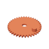
- One "Yoke, Gear (1.5m 38t).stl".
- One "Yoke, Gear, Axle.stl".
- One "Yoke.stl".
Prior to assembly, I test fitted and trimmed, filed, drilled, sanded, etc. all parts as necessary for smooth movement of moving surfaces, and tight fit for non moving surfaces. Depending on your slicer, printer, printer settings and the colors you chose, more or less trimming, filing, drilling and/or sanding may be required to successfully recreate this model. I carefully filed all edges that contacted the build plate to make absolutely certain that all build plate "ooze" is removed and that all edges are smooth using small jewelers files and plenty of patience.
The model uses threaded assembly, so I used an 8mm by 1.25 tap and die for thread cleaning.
Attachments


Step 2: Assembly.


To assemble the model, I performed the following steps:
- Attached "Yoke, Gear (1.5m 38t).stl" to "Base.stl" using "Yoke, Gear, Axle.stl", making certain the gear spun freely.
- Pressed "Gear, Compound, Mount.stl" onto "Yoke.stl".
- Attached "Gear, Compound (1.5m 12t, 1.5m 24t).stl" to the yoke assembly using "Gear, Compound, Axle.stl", making certain the gear spun freely.
- Soldered 100mm long wires between the motor terminals and coaxial cable connector.
- Pressed the motor into "Rack.stl".
- Pressed "Gear, Motor (1.5m 16t).stl" onto the motor shaft.
- Slid "Slide.stl" into "Slide, Guide.stl" noting the orientation of the small dot on the slide (the dot is used for alignment purposes).
- Attached the slide assembly to the base assembly using two "Bolt (M8 by 1.25, 6mm).stl".
- With the slide centered in the slide guide, and the pin on the yoke gear oriented as shown, I slid the yoke assembly into the base assembly noting the alignment of the holes in the slide and the larger gear of the compound gear.
- Slid the rack assembly onto the base assembly making certain to maintain the previous alignment, and aligning the small dot on the smaller compound gear with the center tooth of the rack.
- Secured the rack assembly to the base assembly using two "Bolt (M8 by 1.25, 6mm).stl".
With assembly complete, I applied 4.5VDC power to the model and tested the stroke lengths to make certain the slide movement was centered within the slide guide.
And that is how I 3D printed and assembled "Rack and Pinion, 3 to 1 Stroke".
I hope you enjoyed it, and stay tuned for the automaton!

Participated in the
Made with Math Contest


