

Introduction: "Walk N' Roll!"


I've designed, 3D printed and assembled a number of rolling and walking mechanisms, but never a rolling AND walking mechanism, so "Walk N' Roll!" is my first attempt at a walking and rolling "transformer" mechanism.
Two cams control when the mechanism rolls and walks, and the same two cams create the walking motion for the four legs. Each leg contains a "one way" wheel that allows each wheel to roll when the leg moves from back to front and lock when the leg moves from front to back. This allows the model to walk forward. By simply reversing the polarity of the battery, the model will roll backwards then walk forwards.
As usual, I probably forgot a file or two or who knows what else, so if you have any questions, please do not hesitate to ask as I do make plenty of mistakes.
Designed using Autodesk Fusion 360, sliced using Cura 4.12.1, and 3D printed in TPU and PLA on Ultimaker S5s.
One final note, I receive no compensation in any form for the design, parts and/or materials used in this model.
Supplies
- Soldering iron and solder.
- Thick cyanoacrylate glue.
- Double sided tape.
Step 1: Parts
I acquired the following parts:
- One "uxcell 16mm DC 6V 60RPM Speed Torque Gear Box Electric Motor for Robot".
- One 3.7V 1200mAh lithium battery (https://www.adafruit.com/product/258).
- One JST PH 2-Pin Cable (https://www.adafruit.com/product/3814).
- Four 9.2mm lengths of 2mm diameter music wire (used as leg wheel axles).
Unless noted otherwise, I 3D printed the following parts in PLA at .15mm layer height, 20% infill and no supports.
- One "Arm, Left.stl".
- One "Arm, Right.stl".
- Two "Axle, Cam.stl".
- Four "Axle, Leg.stl".
- One "Cam, Left.stl".
- One "Cam, Right.stl".
- One "Chassis Base.stl".
- One "Chassis, Left.stl".
- One "Chassis, Right.stl".
- One "Gear and Axle, Wheel (2m 12t).stl".
- One "Gear, Cam (1m 48t).stl".
- One "Gear, Motor (1m 12t, 2m 12t).stl".
- Two "Gear, Wheel (2m 12t).stl".
- One "Leg, Left, Front.stl".
- One "Leg, Left, Rear.stl".
- One "Leg, Right, Front.stl".
- One "Leg, Right, Rear.stl".
- Two "Wheel Well, Left.stl".
- Two "Wheel Well, Right.stl".
- Four "Wheel, Foot.stl" in TPU on a TPU raft.
- Four "Wheel.stl" in TPU on a TPU raft.
This is a high precision print and assembly model using at times very small parts and in very tight spaces. Prior to assembly, test fit and trim, file, sand, etc. all parts as necessary for smooth movement of moving surfaces, and tight fit for non moving surfaces. Depending on you printer, your printer settings and the colors you chose, more or less trimming, filing and/or sanding may be required. Carefully file all edges that contacted the build plate to make absolutely certain that all build plate "ooze" is removed and that all edges are smooth. I used small jewelers files and plenty of patience to perform this step.
The model also uses threaded assembly thus an M8 by 1.125 tap and die will assist with thread cleaning if necessary.
Attachments
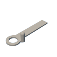
 Arm, Left.stl
- Arm, Right.stl
- Axle, Cam.stl
- Axle, Leg.stl
- Cam, Left.stl
- Cam, Right.stl
- Chassis Base.stl
- Chassis, Left.stl
- Chassis, Right.stl
- Gear and Axle, Wheel (2m 12t).stl
- Gear, Cam (1m 48t).stl
- Gear, Motor (1m 12t, 2m 12t).stl
- Gear, Wheel (2m 12t).stl
- Leg, Left, Front.stl
- Leg, Left, Rear.stl
- Leg, Right, Front.stl
- Leg, Right, Rear.stl
- Wheel Well, Left.stl
- Wheel Well, Right.stl
- Wheel, Foot.stl
- Wheel.stl


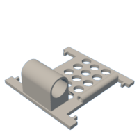


Step 2: Chassis Base Assembly.


To assemble the chassis base, I performed the following steps:
- Slid the wires from the JST connector through the small tunnel in "Chassis Base.stl".
- Pressed the motor into the base assembly, then soldered the wires to the motor such that the motor runs clockwise when viewed from the motor shaft end of the motor.
- Pressed "Gear, Motor (1m 12t, 2m 12t).stl" onto the motor shaft.
Step 3: Chassis Left Assembly.


To assemble the chassis left side, I performed the following steps:
- Placed "Arm, Left.stl" into "Chassis, Left.stl" such that the left arm pin faced outward.
- Positioned "Cam, Left.stl" on the left chassis assembly such that the left arm pin was inside the left cam slot.
- Pressed one "Axle, Cam.stl" through the outside of the left chassis assembly then through the cam (a small dot of glue may assist in retaining these components).
- Pressed "Gear, Cam (1m 48t).stl" onto the cam axle (a small dot of glue may assist in retaining these components).
Step 4: Chassis Right Assembly.


To assemble the chassis right side, I performed the following steps:
- Placed "Arm, Right.stl" into "Chassis, Right.stl" such that the right arm pin faced outward.
- Positioned "Cam, Right.stl" on the right chassis assembly such that the right arm pin was inside the right cam slot.
- Pressed the remaining "Axle, Cam.stl" through the outside of the right chassis assembly through the cam (a small dot of glue may assist in retaining these components).
Step 5: Leg Assembly.


To assemble the legs, I performed the following steps:
- Positioned one "Wheel, Leg.stl" into "Wheel Well, Left.stl", secured in place with one of the 9.2mm by 2mm axles, and made certain the wheel rotated in the wheel well with ease.
- Glued the assembly onto "Leg, Left, Front.stl".
- Repeated the previous two steps with "Leg, Left, Rear.stl".
- Repeated the previous three steps with the "Leg, Right, Front.stl" and "Leg, Right, Rear.stl" using "Wheel, Well, Right.stl".
Step 6: Final Assembly.


For final assembly, I performed the following steps:
- Carefully aligned the right cam axle with the cam axle, the cams, and the left and right chassis assemblies, I pressed the chassis side assemblies onto the base assembly.
- Positioned the left front leg assembly and one "Wheel.stl" on the chassis assembly making certain the pin on the left front leg was in the slot in the left arm, secured in place with one "Axle, Leg.stl", then made certain the wheel and leg rotated freely.
- Repeated the previous step for the right front leg assembly.
- Positioned "Gear, Wheel (2m 12t).stl" into the chassis assembly.
- Positioned the left rear leg assembly on the chassis assembly making certain the pin on the left rear leg assembly was in the slot in the left arm.
- Positioned one "Wheel.stl" on the chassis assembly centered over the left rear leg and secured it and the left rear leg assembly to the chassis assembly with one "Axle, Leg.stl", then made certain the wheel and leg rotated freely.
- Pressed "Gear and Axle, Wheel (2m 12t).stl" onto the wheel gear (a small dot of glue may assist in retaining these components).
- Slid the remaining "Gear, Wheel (2m 12t).stl" through the right chassis and pressed it into the wheel gear and axle (a small dot of glue may assist in retaining these components).
- Positioned the right rear leg assembly on the chassis assembly making certain the pin on the right rear leg assembly was in the slot in the right arm.
- Positioned the remaining "Wheel.stl" on the chassis assembly centered over the right rear leg and secured it and the right rear leg assembly to the chassis assembly with the remaining "Axle, Leg.stl", then made certain the wheel and leg rotated freely.
With assembly complete, I secured the battery to the chassis underside using double sided tape. I then plugged the battery into the JST connector, and off it went!
And that is how I 3D printed and assembled "Walk N' Roll!".
I hope you enjoyed it!


