

Introduction: 5-axis CNC Cut Photo


This is how to create a 5-axis CNC cut photo, a project in collaboration with James Yett, using the same methods as the 3d printed photo (https://www.instructables.com/id/3d-printed-photo/).
The concept works on the basis of a diffuse reflection on a surface from a single light source http://en.wikipedia.org/wiki/Diffuse_reflection . When a surface is oriented so that it reflects the light source towards your eye, it appears to be a brighter color. When the light is reflected away, it appears darker.
If the surface texture is fairly rough you will have a more diffuse reflection and most of the brightness of the light is scattered. This works best with a darker material since a lighter color will absorb less light and the light source will be less visible. If the surface is polished, you will get more specular reflection and the light source will appear brighter, allowing for a lighter color material.
To create the oriented surfaces, I used Autodesk's Dynamo which is a free graphical programming environment for Vasari or Revit (get Vasari for free at www.autodeskvasari.com and Dynamo at www.dynamobim.org). You will also need Solidworks with HSMworks (www.hsmworks.com) to generate the 5-axis toolpaths.
Step 1: Working With the Dynamo File


Start by downloading and installing Vasari and Dynamo. When you first start up Vasari, on the left it will say Projects and Families. Click the button that says "New Conceptual Mass". Open the default "mass.rft" template. In Vasari under the "Add-Ins" tab, click the button for Dynamo.
In the Dynamo window, open the file (provided below) cnccutphoto.dyn.
You will see the graphical program to create the image. An image is read by it's rgb pixel values in a list. The rgb values are translated into greyscale values. These values are translated into a range for -x to x for our surface rotation. A grid is created matching the number of pixels in the image and a circle is created at each grid point. Then each circle is rotated based on its corresponding greyscale value. That circle is extruded as a surface for Solidworks to reference its shape and normal.
At the far left of the Dynamo file is all the parameters to create your image.
The first box "File Path" is where you will open the image file you want to create. Make sure the image is square, has good contrast in greyscale, and the pixel number is even (30, 50, 100 etc.). I used a photo of myself.
Next choose your image size. This is measured in millimeters from the center of circle to circle.
Choose your pixel number. This needs to be the same number of pixels in your image or evenly divisible.
The "Max Rotation" parameter is the maximum rotation of the surface for a black or white value. 15 degrees is a good place to start.
"Overlap" sets the radius or the circles. It's best to have each circle overlapping each other completely or not at all.
"Thickness" will set the extrusion distance for each circle. This will be the depth of your cut (1mm is good).
Lastly, the file will need to be exported as a SAT. Set the last "File Path" to where you would like it to save and remember to keep the extension as ".sat". Every time you click run, a new file will be written to that path.
Attachments

Step 2: HSMWorks Toolpaths


Start up Solidworks and open the .SAT file you created. This can take some time for Solidworks to translate the geometry. Once translated you should have a bunch of imported surfaces. If your model is giant or tiny, Dynamo may have your units wrong. If it's not right, open the .sat file in a text editor and look at the first number in the 3rd line. This is the model units per millimeter. If it is something other than 1, change it and save the file.
To set up the part for machining, you need to start with stock geometry. Start a sketch on the front plane and draw a box around your model. Next turn this sketch into an extruded boss and make sure the extrusion is thicker than your model in both directions. Try to make the top surface as close to the model geometry as possible.
Click the Job folder in the HSM tab to set up your project. Set the stock as a solid and choose your extruded stock (you can hide it after this) and load your machine configuration.
Now make a 2d pocket. Choose a tool that is slightly smaller than your circles so the tool has room to clear the pocket. For machining acrylic, I set the speeds to 17,000 rpm and a cutting feed rate of 100 ipm. I set the ramping and plunge feed rates to 75 ipm.
For model geometry, choose the bottom edge of a circle in a corner to start. Then for tool orientation, choose the surface of that circle. Remember to uncheck "stock to leave" in the passes tab. I the ramping section, choose "Plunge" for the style of ramping.
Now you have a pocket set up for one surface. You could repeat these steps hundreds of times but you don't have to. Right click the pocket tool path and click "Add to New Folder". Then right click that folder and click "add pattern".
In the pattern dialog, choose "Duplicate Pattern". Pick the surface you set up the pocket on as your reference and pick the rest of the surfaces to duplicate. You should now have hundreds of 2d pockets.
Run a machine simulation on the entire folder to make sure everything looks right and post your code!
Step 3: Machining Acrylic


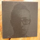
I machined mine out of a 30"x30"x1/4" sheet of black cell cast acrylic. Cast acrylic is supposed to be better for machining than extruded acrylic because of its polymer composition. I drilled holes around the perimeter with a zero rake drill bit, added double stick tape to the bottom and screwed it down to a piece of MDF.
Machining took about 7 hours total for me for a 50x50 image with 3/8" pockets.
My speeds and feeds may not have been great. I ended up with about 30% of the pockets rough from the plastic overheating. This is a problem with colored acrylics since the color disappears at higher temperatures. I tried flame polishing the rough areas with no luck. This piece ended up being painted black rather than just polishing.
Step 4: Mount and Enjoy!


There may be other ways to achieve the same results, even with a 3 axis CNC machine. Feel free to experiment with the code, geometry, software and materials to see what else is possible. A wood or metal version might look great.
Enjoy and remember to share what you've learned here!


