

Introduction: Adding a Microphone to Pi Pico W on Pimoroni Galactic Unicorn


The Pimoroni Galactic Unicorn is a 53x11 RGB LED display from Pimoroni's Unicorn series based on a Pi Pico W board. This article looks at how to add a small analogue microphone to the Unicorn.
Pimoroni's Space Unicorns have two Qwiic/STEMMA QT connectors which are great for connecting i2c peripherals but microphones do not use the i2c protocol. These connectors are also not suitable for the use of the i2s protocol for digital microphones. The four GPIO pins used for these connectors are not analogue-capable ruling out connection to an analogue microphone. The three analogue-capable pins on the Pi Pico W are used on the Unicorns - this article looks at reusing the most suitable one to connect to an analogue microphone.
Analogue microphones designed for use with microcontrollers are ideal, the SparkFun Sound Detector is one example of these. It has various outputs including an amplified analogue audio output from its electret microphone.
The addition of a microphone requires some careful soldering and may involve crimping.
UPDATE: An example application can be found in Instructables: Making a Guitar Tuner and Audio Spectrum Analyser Using the Pimoroni Galactic Unicorn.
Supplies
- Pimoroni Galactic Unicorn - Pimoroni - Pimoroni's other Space Unicorns are viable but pixel layouts aren't ideal.
- Sparkfun Sound Detector - Mouser - an amplified analogue microphone with some additional features.
- Three 30cm (12") individual wires with DuPont female connector or five wires to a single DuPont female connector.
- Optional
- 5pin single row right-angled male header.
- 5x1 (at least) female "DuPont" connector with pins.
- A suitable crimping tool or a willingness to improvise with some dexterous use of pliers and soldering.
- Solder and soldering iron.
Step 1: The Microphone Connectivity Challenge


The common interfaces for microphones used by hobbyists are:
- analogue,
- pulse-density modulation (PDM),
- i2s bus.
The Pimoroni Space Unicorns have two Qwiic/STEMMA QT which provide i2c pins. These are just GPIO pins from the Pico so could be used for other protocols. Unfortunately an i2c bus uses an open collector design which requires pull-up resistors and these are provided as a pair of 5.1k resistors on the Unicorn which cannot be disabled. The i2s bus uses push-pull, this means the GPIO cannot be converted for i2s use without unsoldering the surface mount resistors.
These Unicorns unfortunately use all three of the analogue-capable pins on the Pi Pico (W). These are listed below.
- GPIO28 (ADC2) LIGHT_SENSE - output from the phototransitor and 1k resistor potential divider.
- GPIO27 (ADC1) SW_STANDBY - button to ground.
- GPIO26 (ADC0) SW_REDUCE_VOLUME - button to ground.
Fortunately, there are no external components on the button lines and the buttons are momentary-actionpush to make - if they are not pressed the GPIO are not connected to any external hardware. The SW_STANDYBY button is marked Zzz on the front of the Unicorns and for many applications will not be needed. This makes it a very tempting target to reuse as an analogue input.
The SparkFun Sound Detector can be connected with the following wiring:
- AUDIO to GPIO27,
- VCC to 3V3(OUT),
- GND to Pico AGND.
The Zzz button is implemented with an internal pull-up resistor. The program will need to reconfigure GPIO27 after the Unicorn library code has configured it as a pull-up.
If the Zzz button is pressed while a microphone is attached then the AUDIO output will be connected directly to ground. The Sound Detector board has a 100 ohm resistor after the op-amp which drives the AUDIO output. This will limit the average current to 1.65V/100ohms = 16.5mA. That small, brief current should be safe for the LMV324 op-amp if the button is accidentally pressed.
Step 2: Selecting a Microphone

The previous page described how an analogue microphone is an attractive option for the Space Unicorns. The relevant features for a microphone module are:
- Essential:
- 3.3V compatible;
- does not produce negative audio output voltages.
- Useful:
- produces an output which covers the most of or the full voltage range of the ADC, 0V-3.3V with silence equating to voltage (DC offset) around 1.65V;
- ideally offers some form of control over the gain for the microphone. Automatic gain control (AGC) may be desirable or undesirable depending on the application(s).
Three suitable microphone boards are shown above, clockwise from top left:
- Adafruit Electret Microphone Amplifier - MAX9814 with Auto Gain Control
- SparkFun Sound Detector
- Velleman Microphone sound sensor (WPSE309)
There will be many more, this is just a sample set. The SparkFun Sound Detector was selected based on good availability and some extra features that could be useful in other projects.
Step 3: Pi Pico W Connection


The Pi Pico (W) pins needed to connect the microphone are
- pin 36 3V3(OUT),
- pin 33 GND / AGND,
- pin 32 GP27 / ADC1 / I2C1 SCL.
The microphone wires can either be
- soldered directly to the Pi Pico pads or
- a male header can be soldered onto the pads to provide a more flexible connectivity solution.
These pads are close to each other allowing a 5pin header to be used to span all the required pads. A right-angled header is useful here because the Pi Pico W is close to the edge of the Galactic Unicorn and the Unicorn may be used standing upright on a desk.
Test the Galactic Unicorn before and after the soldering. The pre-loaded demo software is useful for this.
Soldering Wires
Apply a small amount of solder to the three pads first to mark them. Tin (apply solder to) the wires. Then solder the two together. This process should help to minimise the heat applied to the pad.
Soldering A Header
If you have no intention of using pins 34 (GP28) and 35 (ADC_VREF) in the future then you can remove or trim the pins. The pins can be easily pulled out with pliers. A pair of cutters can be used to trim the pins but these are substantial, solid pins and are likely to fly at high speed across your room as you cut them. Eye protection is a wise precaution if you are going to cut them.
Lightly soldering one end pin to physically hold and locate the header is a good first step. The other pins can then be soldered and the first pin can be resoldered. Angling the pins 5-10 degrees towards the centre of the Unicorn may help to keep the header/connector clear of the surface if the Galactic Unicorn is used on its stand.
The idea for using header pins originated from a discussion in the Pimoroni forums.
The soldering should be as brief as possible to reduce the risk of the underside of the Pi Pico W board heating up too much. There is a small chance the module could become partially unsoldered from the Unicorn board if lots of heat is applied. Lead-based solder has a lower melting point and tends to flow better than modern lead-free alternatives making it attractive for this small task.
Take care not to touch the components on the Pi Pico W board with the soldering iron. Note: there is a transistor very close to the GND pad.
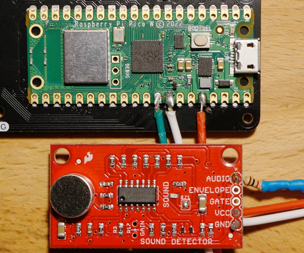
Step 4: Sound Detector Board Connection


The SparkFun Sound Detector has five pads, for the Pi Pico only three will be used:
- AUDIO - a cable colour other than red or black;
- VCC - ideally a red cable;
- GND - ideally a black cable.
The photograph above has brown as the new black. The red cable bends around underneath the board to connect to VCC.
The three wires from the microphone board will either be soldered directly to the Pi Pico W or terminated with a "DuPont" connector.
Adapting 5 way cable to Female "DuPont" connector
Premade cables can be purchased with connectors. The colours are unlikely to match the desired ones. The unused pins can be removed by prising up the thin black plastic tab that locks them in and then pulling the cable.
See below for tips on blocking the two unused pins to key the connector.
Adding 5pin Female "DuPont" connector
The three wires need to be crimped to female metal pins and then inserted in the correct position into the header. These articles/videos will help if you have not done this before.
- Instructables: Make a Good Dupont Pin-Crimp EVERY TIME!.
- Andreas Spiess: #12 Five Tricks for working with Dupont wires (YouTube).
Andrew Spiess has a review of different crimping tools in Andreas Spiess: #282 Crimpers: IWISS IWS-2820M against Engineer PA-09? (YouTube).
For those without a crimper the female metal pins can also be carefully squashed with needle-nose pliers. This is unlikely to provide a reliable connection. A very light soldering, taking care not to put solder in the "mating pin zone", will create a good electrical and mechanical connection.
There are two unused pins on the header. These can be blocked with keying pins or an improvised blockage using glue which sets and/or thin strips of plastic. This will prevent the header being attached with an incorrect orientation.
Using 3 DuPont wires with individual female "DuPont" connectors
This is a simple alternative approach but it means each time the microphone is connected the pin order needs to be correct. This is more prone to accidents which may damage the microphone module.
The SparkFun board comes with the microphone pins untrimmed. A quick snip with a pair of cutters will make these less obtrusive.
Step 5: Going Further

Once you've attached a microphone it's time to use it. A future article will cover adaptation of the Blunicorn software (see link below) to use the analogue microphone and to add extra functionality like a waterfall spectrogram and an instrument (guitar) tuner.
Related projects:
- Hackster.io: Henri: Pico Wake Word
- Hackster.io: Alex Wuff: ADC Sampling and FFT on Raspberry Pi Pico
- V. Hunter Adams: Realtime Audio FFT to VGA Display with RP2040 (Raspberry Pi Pico) - part of Cornell University's Digital Systems Design Using Microcontrollers (ECE 4760/5730) course.
- Phil Howard's Blunicorn - "a Bluetooth A2DP Speaker Firmware for the Raspberry Pi Pico W-powered Galactic Unicorn and Cosmic Unicorn from Pimoroni". This reads audio from a Bluetooth source, not analogue pins.
- Instructables: Galactic Unicorn Graphical Workout
Further reading:


