

Introduction: EMG With Arduino UNO R4 WiFi and DIY Neuroscience Kit From Upside Down Labs


The DIY Neuroscience Kit - Pro from Upside Down Labs is an Arduino UNO centred kit for sensing biopotentials. Upside Down Labs state it's capable of sensing:
The Pro version of the kit comes with an Arduino*** UNO R3, a BioAmp EXG Pill board and a Muscle BioAmp Shield. The Pill and the shield are based on the Texas Instruments TL084PW and LM324N amplifiers, respectively. These can magnify the tiny voltages from electrodes placed on the skin to a level suitable for the analogue inputs on an Arduino microcontroller.
This article looks at using the fairly new Arduino UNO R4 WiFi with the kit to display the output from the Bioamp EXG Pill on the 12x8 LED display as a bar chart and to control a servo. The gain from the hardware amplification and software filtering is explored and shown with theoretical plots.
** The kit is not a medical device with IEC 60601 certification.
*** The board supplied in my Pro kit appears to be a low-quality, counterfeit Arduino board. The basic kit uses the excellent Cytron Maker Uno.
Supplies
- DIY Neuroscience Kit – Pro: Upside Down Labs (for India) | Tindie (for International) | DigiKey
- or DIY Neuroscience Kit - Basic: Upside Down Labs (for India) | Tindie (for International) | DigiKey
- Arduino UNO R4 WiFi: DigiKey | Arduino Store
- Ideally a laptop.
- A USB power bank is useful to power the Arduino.
Step 1: Contents of Kit


The Pro kit contents can be seen in the above photographs. It contains:
- An Arduino UNO R3** with 30cm USB lead.
- A BioAmp EXG Pill.
- A Muscle BioAmp Shield v0.3 - this includes many connectors and six LEDs.
- Servo with claw attachment.
- Various connecting cables.
- Many electrodes.
- Four electrode bands.
- Electrode gels, skin cleanser and wipes.
- Single page leaflets about EXG Pill and Muscle Shield.
There's a video description of the contents on YouTube: Upside Down Labs: Unboxing DIY Neuroscience Kit Pro.
** In my kit, this appears to be a counterfeit board. It has Arduino UNO R2 branding and claims to be "made in Italy" but its headers are too far apart and not straight on the top row making it difficult to attach the shield. It came in just an anti-static bag, has no image of Italy on the underside silk screen, has a red reset button (R3 is white) and the reset enable is marked REGET ON. It did not come with a plastic base to prevent the underside from scratching a desk.
Pro vs Basic Kit
The basic kit differs in the following way:
- A Cytron Maker Uno replaces the Arduino. This has 12 LEDs on the digital pins, uses a micro-USB connector and has a flat underside.
- It does not include the Muscle BioAmp Shield, the servo with claw and has one rather than two Muscle BioAmp Bands.
Step 2: Arduino UNO R3 Vs R4 Minima and R4 WiFi


The Arduino UNO wikipedia page has a very good summary of the differences. Two images of genuine boards are shown above borrowed from the Arduino site. Here are some highlights.
- UNO header remains the same but the R4 has handy labels on the inside and outside.
- R3 has "old" USB-B connector, R4 has USB-C.
- R4 has a 48MHz 32bit RA4M1 (ARM) microcontroller with FPU, R3 has 16MHz 8bit ATmega328p CPU.
- R4 has 256KB flash storage, 32K static memory, 8K EEPROM vs R3 32KB/2KB/1KB.
- R4 WiFi has 12x8 charlieplexed red LED display, an additional Espressif ESP32-S3 coprocessor for WiFi and one Quiic connector.
- R4 has a 12bit DAC for true analogue output. This isn't particularly relevant to this article but it's a useful addition for other projects.
Step 3: Finding a Good Place
Upside Down Labs recommend sitting 5m away from any AC (mains powered) appliances and to use a laptop disconnected from the mains if the Arduino UNO is to be powered by a computer during sensing.
The NoiseBarGraph.ino software (see the next step for notes on how to install software on an Arduino) for the Arduino UNO R4 WiFi is a primitive attempt to show the level of interference present in a location using just one wire. This shows the
- logarithmic value of envelope of the signal from the A0 input on the upper half of the display and
- the same signal filtered to avoid mains fundamental frequencies on the lower half.
This can be used as a crude gauge to quickly survey the the suitability of potential locations. A battery-powered Arduino can be placed in each location on an insulated base/surface and while holding only the metal pin of a male-male jumper wire (not included in the kit) connected to A0 the bar graph values can be read. Do not hold the Arduino or the battery as this may affect the values. Here are some values from some typical home locations quoted as the number of illuminated LEDs on the upper & lower bar graphs, 48 is the maximum per graph.
- Desk 1 with desktop computer on: 48 & 32.
- Desk 2 with nothing on but lots of nearby mains cables: 48 & 33.
- Bathroom: 42 & 7.
- Sofa: 42 & 1.
- Bed 1 (shown above): 42 & 15.
- Bed 2: 42 & 6.
The sofa is a tempting location based on this quick survey due to its lowest filtered value.
The following are worth avoiding/studying as potential sources of interference.
- Fluorescent lights are a traditional source of ExG interference. These are becoming rare in the home environment but it may be worth experimenting during the day with natural light only vs other lights with caution on dimmable lights and low voltage lights powered by an "electric transformer".
- Any transmitters like a mobile phone or WiFi enabled devices may cause interference.
- Powered uncased electronics like a nearby Raspberry Pi could also be problematic interference sources.
Step 4: Exploring the BioAmp EXG Pill for EMG With ClawController

The small leaflet for the BioAmp EXG Pill has a QR code which takes you to https://docs.upsidedownlabs.tech/docs/BioAmp-Hardware/BioAmpEXGPill. From there the navigation on the left can take you to the DIY Muscle BioAmp Shield documentation.
The GitHub repository for the BioAmp EXG Pill can be found with an Internet search and includes some software to control the servo-based claw. ClawController.ino is an enhanced version of this which displays a bar graph on the 96 LEDs which form the Arduino R4 WiFi's display.
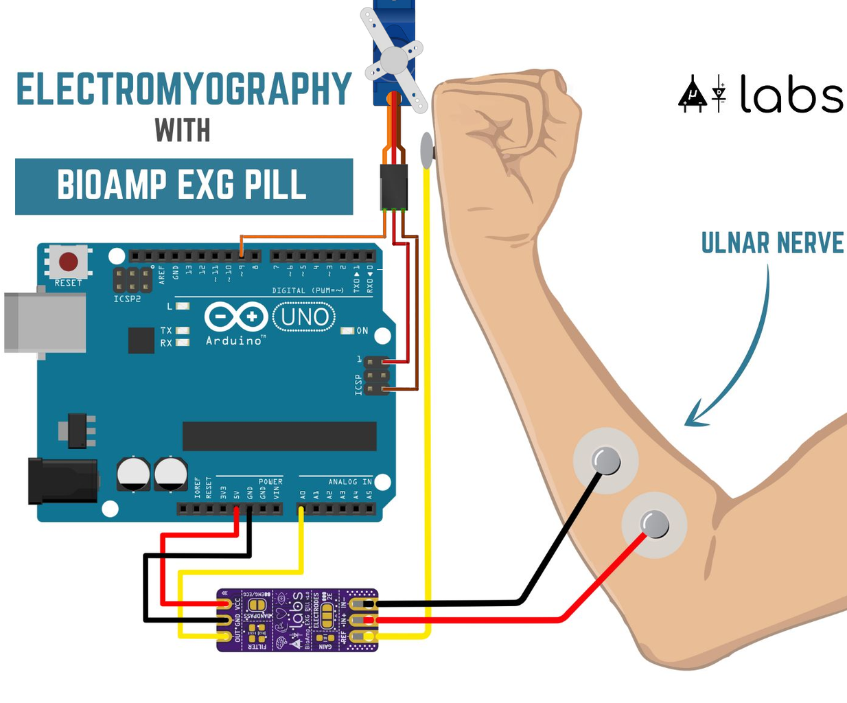
Connecting the Hardware
The diagram above shows how to connect the Arduino UNO to the BioAmp EXG Pill:
- UNO GND wire (black) to Pill GND;
- UNO 5V wire (red) to pill VCC;
- UNO A0 wire yellow to pill OUT.
It is very important to connect the Pill correctly. Carefully connect it with the Arduino unpowered, then verify it again before powering on the Arduino.
The BioAmp EXG Pill then connects to the electrodes with the 1m cable with metal poppers on. This is explained in the video How to use DIY Neuroscience Kit Basic?. The kit includes some cable ties if you want to tidy this cable bundle up.
The program can be used without the servo-based claw attached. The Pro kit includes the claw but does not include cables to connect it directly to the Arduino UNO - the Muscle BioAmp Shield has the connector for the servo. The servo can be attached directly to the Arduino UNO if you have some extra jumper wires (not supplied with the kit):
- UNO ICSP GND a female to male wire for GND (brown substituting for black),
- UNO ICSP 5V another female to male wire for 5V (red) and
- D9 a male to male for the PWM control signal (orange).
The ICSP connector needs to be used here as the UNO only has one 5V pin on its normal headers.
Installing Software on an Arduino UNO
This is a simple guide to installing the sketch - this is the Arduino terminology for a program with file extension .ino. More detail can be found in the Arduino IDE documentation.
- If you do not already have it, install the Arduino IDE 2 software on a desktop or laptop.
- Connect the appropriate Arduino UNO board via USB to the computer.
- Click on the download raw file icon on ClawController.ino - the Arduino IDE expects this to be inside a directory called ClawController.
- Open the ClawController.ino file in Arduino IDE. An alternative method is to cut and paste the program into the Arduino IDE replacing the two empty functions which appear for a New Sketch.
- The boards should shown up in the IDE as Arduino Uno or Arduino R4 UNO WiFi. If you have both connected then ensure the correct one is selected.
- The Upload icon (right arrow) will compile the sketch and upload it to the Arduino board. The yellow RX LED will flash as the compiled code uploads to the board.
- The code will run immediately after its uploaded and remain on the board until it's replaced.
If you are having problems with the compilation it may be worth using the simplest program to test the procedure. The File > Examples > 01.Basics > Blink is a classic test program. It flashes the LED on the board by repeatedly turning it on for a second and then off for a second.
This is the compilation output for Arduino Uno (R3) board.
Sketch uses 6034 bytes (18%) of program storage space. Maximum is 32256 bytes.
Global variables use 703 bytes (34%) of dynamic memory, leaving 1345 bytes for local variables. Maximum is 2048 bytes.
This is the compilation output for Arduino UNO R4 WiFi board. The warning on the first line is harmless.
WARNING: library ArduinoGraphics claims to run on samd architecture(s) and may be incompatible with your current board which runs on renesas_uno architecture(s).
Sketch uses 60024 bytes (22%) of program storage space. Maximum is 262144 bytes.
Global variables use 8140 bytes (24%) of dynamic memory, leaving 24628 bytes for local variables. Maximum is 32768 bytes.
Erase flash

Done in 0.001 seconds
Write 60032 bytes to flash (15 pages)

[               ] 0% (0/15 pages)
[==              ] 6% (1/15 pages)
[====             ] 13% (2/15 pages)
[======            ] 20% (3/15 pages)
[========           ] 26% (4/15 pages)
[==========          ] 33% (5/15 pages)
[============         ] 40% (6/15 pages)
[==============        ] 46% (7/15 pages)
[================       ] 53% (8/15 pages)
[==================      ] 60% (9/15 pages)
[====================     ] 66% (10/15 pages)
[======================    ] 73% (11/15 pages)
[========================   ] 80% (12/15 pages)
[==========================  ] 86% (13/15 pages)
[============================ ] 93% (14/15 pages)
[==============================] 100% (15/15 pages)
Done in 3.428 seconds
Running the program
- Relocate to your chosen low interference location.
- Ensure you are using a battery, a power pack or a laptop that's now disconnected from mains power.
- When the program starts it attempts to set the claw to be wide open with each part opposite the other for ten seconds. You may need to adjust the servo angles in the code for this to work properly. See below for example of setting them to 0 (open) to 95 (just closed) range. It's safer to leave a small physical gap and not set the servo to fully close the claw to ensure the servo isn't constantly trying to force the parts together.
// #define SERVO_MIN 90
// #define SERVO_MAX 180
#define SERVO_MIN 0
#define SERVO_MAX 95
The same software can be used with the Muscle BioAmp shield, this is documented in Upside Down Labs's Instructables: Controlling Servo Claw With Muscle Signals Using Muscle BioAmp Shield.
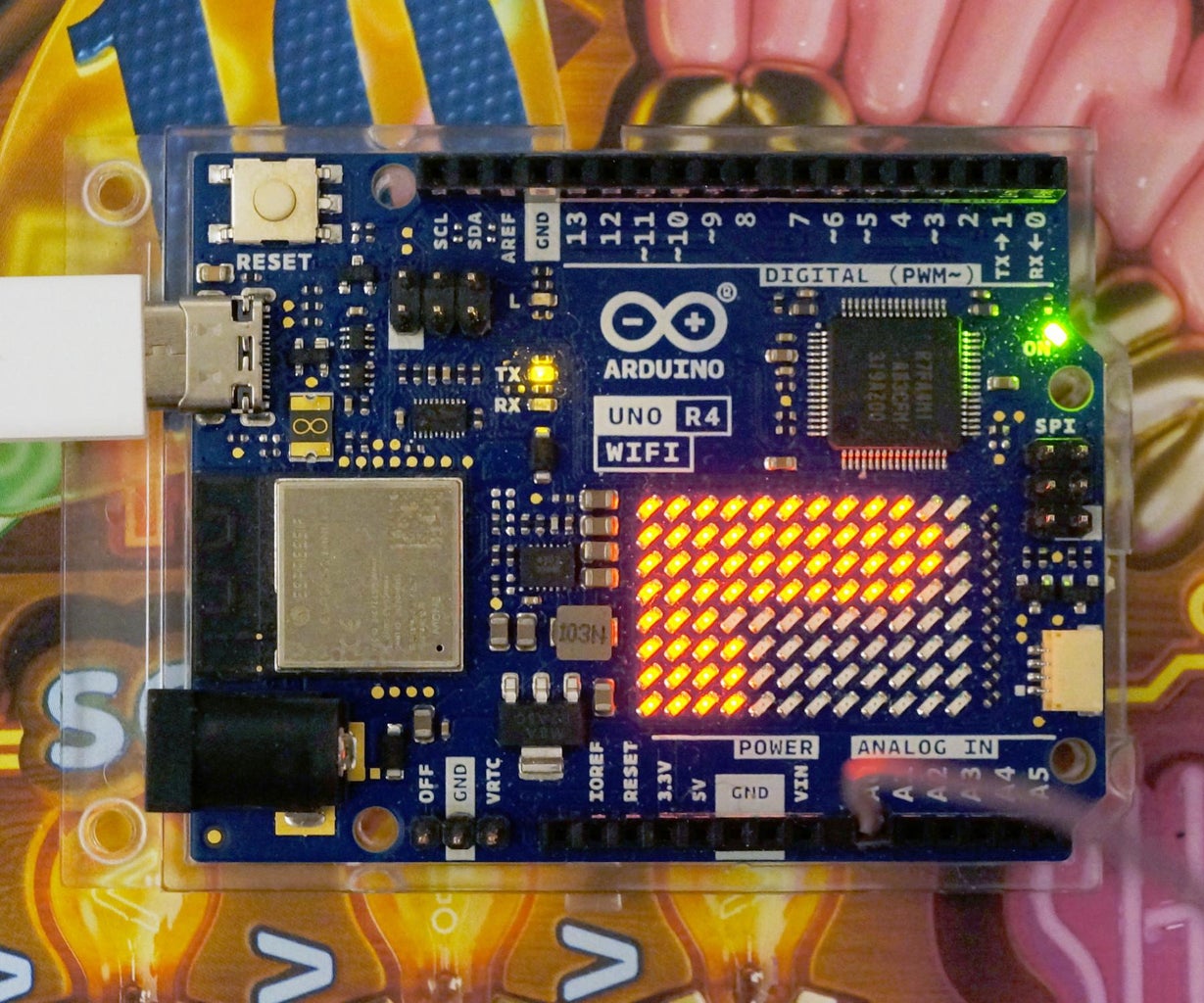
Step 5: ClawController on the Arduino UNO R4 WiFi
The is the BioAmp EXG Pill controlling the servo-based claw and displaying the output as a bar graph on the Arduino UNO R4 WiFi's display. The power is provided by a USB power-pack.
The claw's servo is connected via three jumper wires not included in the kit. This program would work fine without the servo attached and would work on an Arduino UNO R3.
The values from the Pill that are used to control the servo and shown on the bar graph are set in the code, shown below.
#define EMG_MIN 2
#define EMG_MAX 10
It looks like values of 4 to 14 might be worth trying based on the bar graph's response for this particular setup.
The video is a bit grainy due to low light. The original intention was to use some mains-powered lights placed nearby but these had to be disconnected as they produced too much interference!
Upside Down Labs have a similar demonstration using a Cytron Maker Uno in Controlling a Servo claw and LED bar using EMG.
Step 6: Operational Amplifiers (OpAmps)

A set of operational amplifiers (op-amps) form the heart of this kit. Historically, these high gain amplifiers were used to construct analogue computers. In this kit four op-amps (in one integrated circuit) are used to:
- amplify the tiny voltages from the skin;
- reduce the effect of unwanted signals and noise by filtering by frequency;
- and convert the output to be suitable for the 0-5V range of the Arduino Uno's analogue input.
The current colour coding use by the kit for electrode cables and connectors is
- black for negative input (IN- or -),
- red for positive input (IN+ or +),
- yellow for reference input (REF or R or DRL).
The colours have varied in the past so care should be taken with any older cables/components not from the kit.
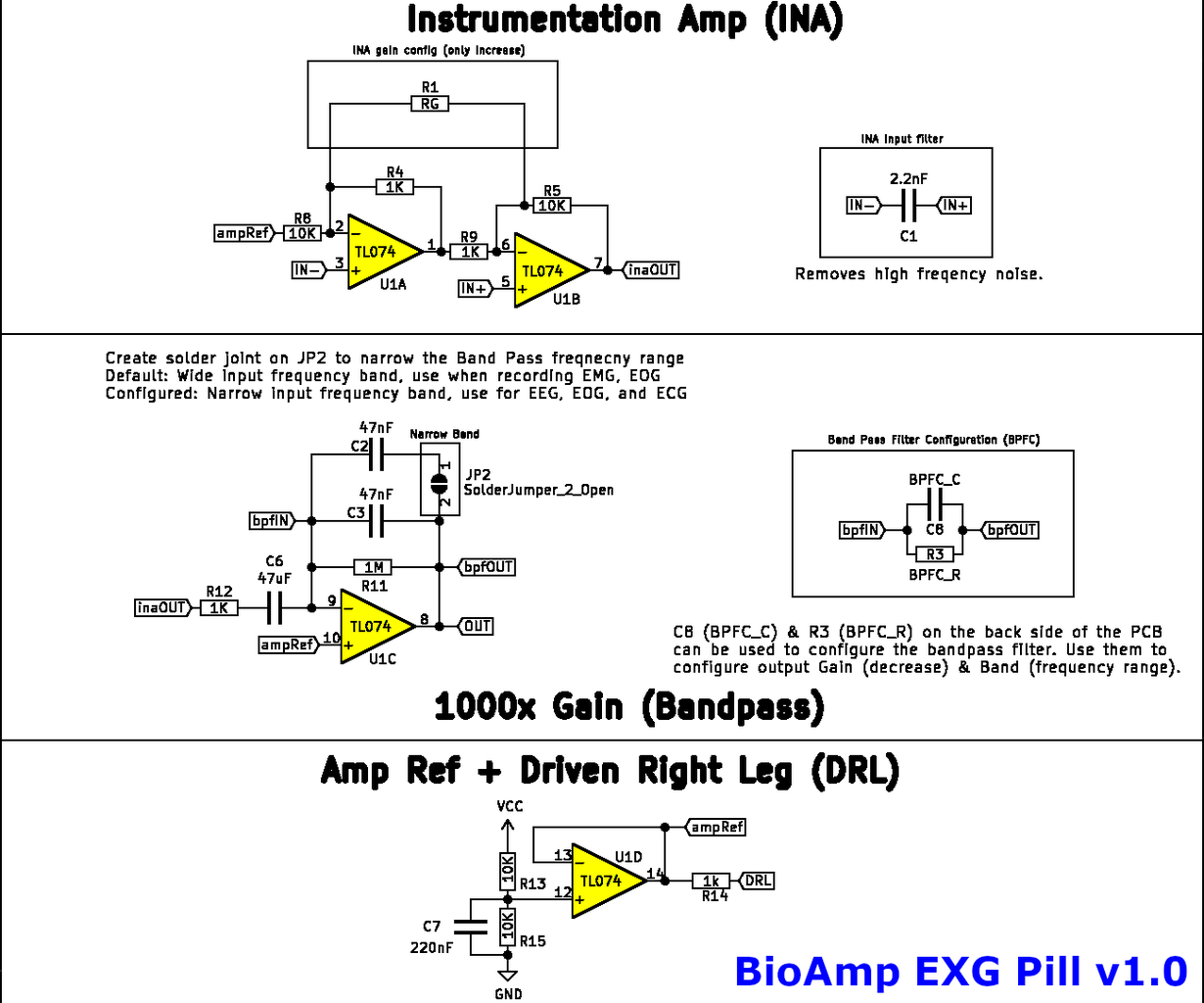
BioAmp EXG Pill v1.0
This uses a Texas Instruments TL084PW (TL074 on schematic) op-amp with 10x gain in its instrumentation amplifier stage and a bandpass filter between 3.39Hz and 3.39Hz (both filter poles are the same). The peak gain of the filter stage would be 1000x but the band is very narrow lowering the gain.
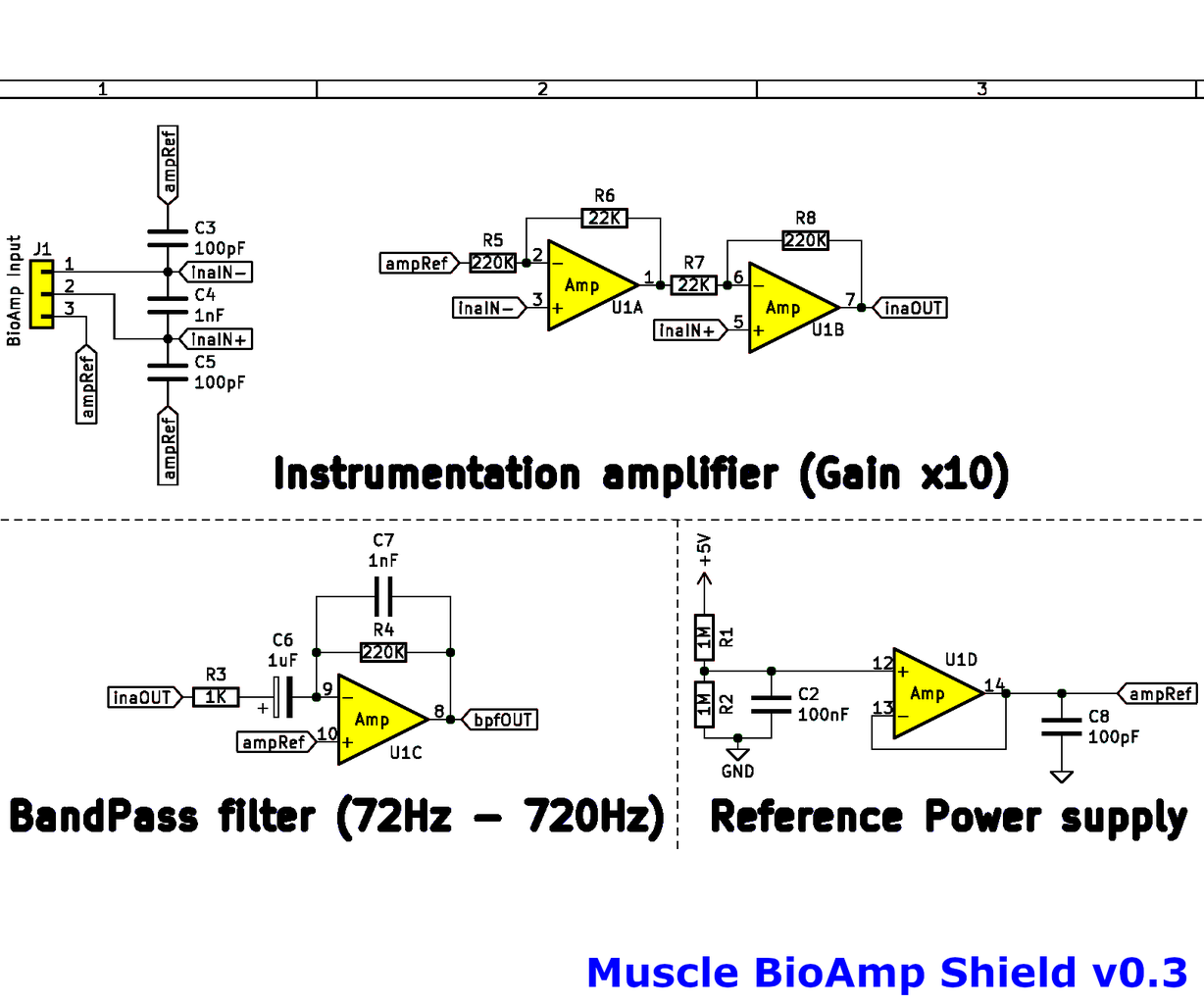
Muscle BioAmp Shield v0.3
This uses a Texas Instruments LM324N op-amp with 10x gain in its instrumentation amplifier stage and a bandpass filter between 159Hz and 723Hz. The peak gain of the filter stage is 220x.
Both boards have capacitors across the input which together with the source impedance will act as a passive low pass RC filter. Filters using op-amps are known as active filters.
The exact frequency response of any filter is dependent on the values of the passive electrical components. These will vary based on the tolerance range which is likely to be wide for capacitors.
Step 7: Powerline Interfence


The images above are familiar to anyone who uses an oscilloscope. The left image is from a Telequipment S51B 5MHz (analogue) oscilloscope and is mains earth grounded reference. The right image is from Scoppy Android App on a tablet connected to a FHDM DS-500K 500ksps digital oscilloscope. Both are showing the result of a finger touching the input.
Touching an oscilloscope input typically causes a messy sine wave to appear with a fundamental frequency of 50Hz or 60Hz depending on where you live, often with a harmonic at 100Hz/120Hz from devices rectifying the mains voltage. The human body is good at picking up (AC) mains electricity via capacitive coupling and also much higher radio frequencies by acting as an antenna.
The BioAmp EXG Pill and Muscle BioAmp Shield have specialised differential inputs which include a Driven Right Leg (DRL) circuit - this is intended to dramatically reduce this type of interference which will mostly be a common-mode signal. There are passive filters on the inputs and active band pass filters on the boards but overall this hardware filtering actually amplifies the powerline interference frequencies. An infinite impulse response (IIR AKA recursive) filter can be efficiently implemented in software to attenuate these frequencies.
Step 8: Software Filtering and Sampling

The Arduino example programs for the BioAmp EXG Pill include various bandpass filters efficiently implemented in software. These
- select the frequency range of interest and also
- significantly reduce the effect of powerline interference.
Upside Down Labs break out the filters into some separate code examples, listed below.
- ECGFilter 0.5Hz to 44.5Hz.
- EEGFilter 0.5Hz to 29.5Hz.
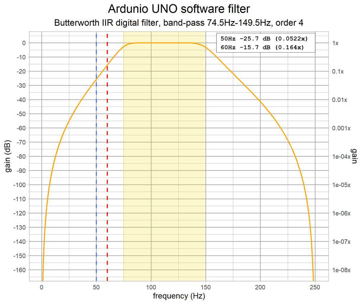
- EMGFilter 74.5Hz to 149.5Hz (same filter as the Muscle BioAmp Shield EMGEnvelope).
- EOGFilter 0.5Hz to 19.5Hz.
The gain of EMGFilter has been plotted using R code and is shown above with linear and logarithmic frequency scales. This is the same filter as the one in the ClawController program. This C code has been generated with Python's SciPy signal library using filter_gen.py. The function is remarkably short and computationally efficient - it shows how efficient IIR filters are compared to their FIR cousins.
The sample rate in the programs is set to 500 samples per second. The Nyquist frequency for this sample rate is 250Hz meaning frequencies above this cannot be correctly sampled and processed. Any frequencies above this limit will cause aliasing artifacts. The board's hardware filters are not designed for a steep roll-off at 250Hz but they will help to reduce the effect of aliasing at higher frequencies beyond approximately 10kHz.
Step 9: Thoughts About the Kit

- The kits are useful for beginners, supplying all the things you might need.
- The Bioamp EXG Pill is very small - take care not to lose it. The documentation says: "Its small size allows easy integration into mobile and space-constrained projects".
- The open source approach for the hardware and software is commendable.
- For using the BioAmp EXG Pill with a 3.3V microcontroller like the Pi Pico, Upside Down Labs recommend adding an external potential divider circuit with 1k and 2.2k resistors. It would be nice to have easier to use, built-in support for 3.3V microcontrollers. This is partly due to the power requirements of the TI TL074/TL084 op-amps.
- One video claims in a caption that the BioAmp EXG Pill "will be damaged" if the VCC and GND are swapped. A mixture of jumper wires and novices make this a likely prospect. If the op-amp is vulnerable then the board should include reverse-polarity protection.
- The kit does not come with an instruction booklet and there is no prominent single QR code / short URL to access the documentation for the kit. There's lots of documentation for various projects in different places. In the absence of an instruction booklet it would be nice to have one (printable) online document or a dedicated index of projects suitable for each kit.
- The lack of feet or a base on the Arduino UNO makes it a desk scratcher.
- The choice of microcontroller boards is good for the kits but it's a poor decision to supply a low-quality, counterfeit Arduino UNO in the (premium) Pro kit. Buying the basic kit, the (pre-assembled) Muscle BioAmp Shield (comes with accessory bundle) and Servo Claw makes more sense.
Step 10: Going Further

There's a range of other projects and ideas to explore in the Upside Down Labs' documentation.
Related projects using other op-amps/products:
- Adafruit Learn
- Getting Started with MyoWare Muscle Sensor
- 'Sup Brows
- Instructables: Typing With EMG Using MyoWare - MyoWare boards with a Makey Makey.
- Cornell University: Capacitively Coupled EMG Electrodes with Finger Gesture Recognition project
- Instructables: ECG Display With Arduino - Peter Balch's project includes a discussion on safety issues wrt IEC 60601, mentioned on Hackaday.io: ECG Project with all the messy safety details.
Further reading.
- Gergely Bencsik: Aliasing explained (YouTube)
- University College London: GZ05: Multimedia Systems: Audio Samples - includes some samples of Equinoxe demonstrating how aliasing can cause undesirable effects.
- NNNI: The BioAmp EXG Pill - An Amazing Little Biopotential Amplifier (YouTube) - a review of the BioAmp EXG Pill demonstrating its output on a Rigol oscilloscope.
- Bortec Biomedical: Important Factors in Surface EMG Measurement (pdf)
- Texas Instruments
- Application Report: Improving Common-Mode Rejection Using the Right-Leg Drive Amplifier (pdf)
- TI ADS129x Low-Power, 8-Channel, 24-Bit Analog Front-End for Biopotential Measurements Datasheet (pdf)
- Medium: Walter Lee: An Unofficial Introductory Tutorial to MyoWare Muscle Sensor Development Kit
- Bruce Winter, John Webster: Driven-Right-Leg Circuit Design
- Boyer, M.; Bouyer, L.; Roy, J.-S.; Campeau-Lecours, A. Reducing Noise, Artifacts and Interference in Single-Channel EMG Signals: A Review. Sensors 2023, 23, 2927
- The Handbook of Human Physiological Recording - an online book by Alan Macy.
- Anatomy and Physiology 2e - a in-depth free book including chapters on the human nervous system.
Similar hobbyist products:
- Advancer Technologies: MyoWare Muscle Sensor
- Backyard Brains: Heart and Brain SpikerBox & Muscle SpikerBox Pro
- Olimex: EEG Analog ASM
Step 11: Appendix: Filter Gain Plots


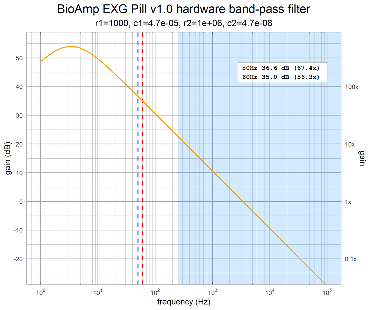


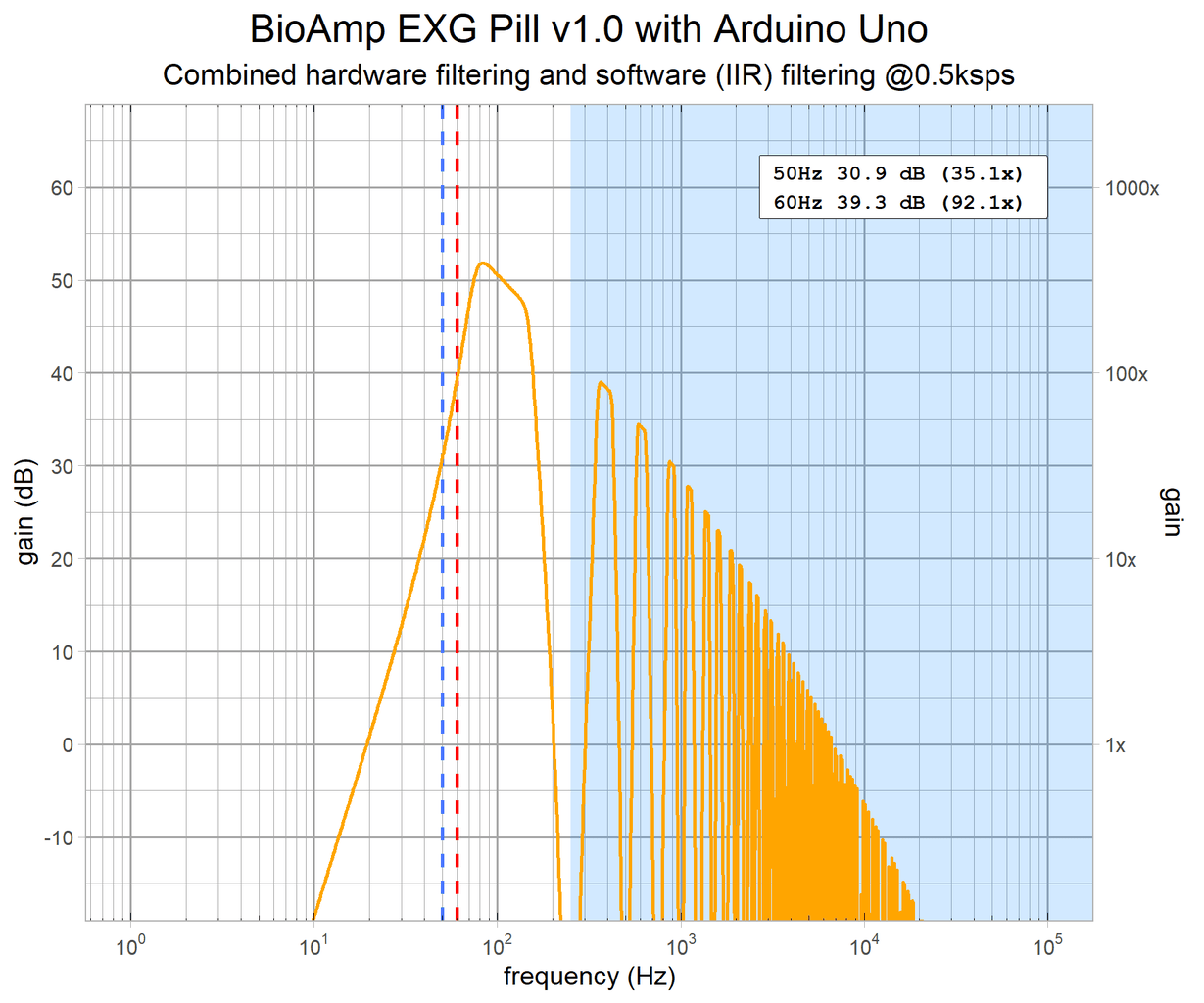


These are the additional gain plots (half of a bode plot) showing how the filtering works on the BioAmp boards. These are calculated, theoretical values, not ones measured from actual board(s). The light blue background shows the frequencies above the 250Hz Nyquist frequency due to sampling at 500sps.


