

Introduction: Exploring and Reducing ADC Noise on Adafruit CLUE (Nordic NRF52840)


This project takes a look at accurately measuring analogue voltages on the Adafruit CLUE using CircuitPython - the same principles apply to all microcontrollers. The CLUE's Nordic nRF52840 microcontroller has a 12bit analogue to digital converter (ADC) which can measure voltages between 0 and 3.3 volts on many of the CLUE's pins.
The 12bit resolution offers 4096 values which equate to voltage steps of 0.806mV. An ideal ADC would return a single, repeatable value when measuring a constant voltage. The power supply and environment are examined as potential contributors causing a deviation from the ideal scenario and typical software approaches for improving accuracy are explored.
A Kitronik :CREATE proto board is used to facilitate soldered connections to the pins. Soldering could be avoided with use of crocodile (alligator) clip leads to the larger P0, P1 or P2 pads on the CLUE's edge connector.
This article follows on from the analysis in Adafruit Learn: CLUE Metal Detector in CircuitPython: ADC Analysis.
Supplies
- Adafruit CLUE: Kitronik | Digi-Key
- Kitronik :CREATE proto board (or similar edge connector adapter): Kitronik
- Switched triple AA holder with JST-PH connector.
- Alligator (Crocodile) clip leads.
- A constant voltage source - an AA battery in a single AA holder is a very cheap starting point.
- Soldering iron, solder and wire strippers.
Step 1: Installing CircuitPython and ADC Logger Program

If you are not familiar with CircuitPython then it's worth reading the Welcome to CircuitPython guide first.
- Install the latest version of CircuitPython (8.1.0 June 2023) from https://circuitpython.org/ - this process is described in CircuitPython for Adafruit CLUE.
- Verify the installation by connecting to the serial console over USB. The REPL prompt shows the version number. The version can also be checked by inspecting the boot_out.txt file on the CIRCUITPY drive.
- Install this library from a recent bundle from https://circuitpython.org/libraries into the lib directory on CIRCUITPY:
- neopixel.mpy - this is the only required library, the others shown in the listing above were used for some command-line testing of an external ADC.
- Download the example program to CIRCUITPY by clicking Save link as... on clue-adc-logger.py
- Download a short program which write enables the storage to CIRCUITPY by clicking Save link as... on boot.py. This file is run once when the CircuitPython interpreter first starts at power-up before the code.py.
- Rename or delete any existing code.py file on CIRCUITPY, then rename the clue-adc-logger.py to code.py. This file is run when the CircuitPython interpreter starts or reloads.
The versions used for this article were:
- CircuitPython: 8.1.0
- CircuitPython library bundle: adafruit-circuitpython-bundle-8.x-mpy-20230630
Step 2: Setting Up the Circuit
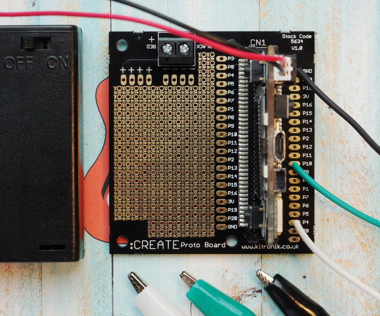
The Kitronik :CREATE proto board is shown above with the three soldered connections:
- GND black.
- P10 green - GPIO acting as a ground.
- P4 white - GPIO set to an ADC input.
The three crocodile (alligator) clips have been soldered too to improve the reliability of the connections. These have a low-quality crimp which may not be perfect to start with and is likely to deteriorate with wiggling from frequent use. There's a useful video on YouTube showing this improvement procedure: Will Bushee: Fixing those cheap Alligator (or Crock) clips from China...
The :CREATE board is designed to allow the Adafruit CLUE (or BBC micro:bit) board to be inserted either way. Not all sockets/adapters for this edge connector permit this.
The constant voltage source (AA battery) connections are:
- positive to white crocodile clip (P4);
- negative to either black (GND) or white (GPIO ground) crocodile clip.
Do not leave the voltage source (AA battery) connected to the CLUE's pins when the CLUE is powered off. It may back power the microcontroller.
Step 3: ADC Sample Values

The circuit simulation above shows a simple 3bit flash ADC illustrating how an ADC works. The flash design uses an array of comparators and some logic gates to create the digital representation in binary. It's quantising a continuous sine wave (bottom left) which varies between 0 and 7.5V, these map to 8 values between 0 and 7. These values can be referred to as ADC codes or quanitsation levels. The voltage range here is larger than a typical microcontroller's ADC can directly measure - the values were chosen for simplicity in the illustration because the digital output is the voltage rounded to the nearest integer volt, e.g. 4.37V is 4 and 4.52V is 5.
Real ADCs range from around 8 to 24 bits and will often be driven by a clock producing samples in discrete time. The ones found on microcontrollers are typically 10-12 bits using the successive approximation design. Some examples are:
- Microchip (Atmel) ATmega328P 10bit 200ksps 0-5V (Arduino Uno).
- Nordic nRF52840 12bit 200ksps 0-3.3V (Adafruit CLUE).
- Microchip ATSAMD21 12bit 350ksps 0-3.3V (Adafruit Circuit Playground Express).
- Espressif ESP32-S2 13bit 0-2.6V (Unexpected Maker FeatherS2).
The values produced by the hardware are fundamentally binary numbers (unsigned integers) which ideally map linearly to the voltage range, e.g. a "perfect" Arduino Uno's ATmega328P would produce:
- 0V = 0
- 1V = 205
- 2V = 409
- 3V = 614
- 4V = 818
- 5V = 1023
This does depend on the Arduino Uno having a good power supply. It requires a minimum 7V supply to allow its regulator to produce a stable 5V supply. If there's no voltage on the barrel connector it relies on the 5V voltage supplied over the USB cable. For Arduino programming the supply voltage is the default reference voltage for the ADC which sets the full scale (FS) value. Andreas Spiess describes this and how to adjust results for incorrect power supply voltages in #10 Tutorial: Make the Arduino Analog Readings more precise (YouTube).
On microcontrollers the ADC reference voltage may be configurable to internal or external references. There may also be a programmable gain amplifier (PGA) offering a few levels of attenuation. The values may be translated and/or corrected for offsets and linearity in hardware or software.
There are often oversampling modes which in some cases can offer improved accuracy and slightly higher precision by averaging multiple samples. The sample rate of the ADC may be able to be increased with some loss of accuracy.
Higher resolution ADCs tend to be external components used for specialist applications on carefully designed boards. Hi-fi audio boards are good examples, for example the Bela uses the 16bit Texas Instruments TLV320AIC3104 codec, the Axoloti uses the 24bit Analog Devices ADAU1961WBCPZ codec and the Daisy Seed (used on SynthUx Academy PCB) uses the Cirrus Logic WM8731 codec.
Espressif's ADCs appear promising from the high level specifications but need to be used with caution as they have various combinations of poor linearity, inability to measure small voltages, limited upper value below microcontroller's voltage and inaccurate documentation.
Arduino API
The Arduino API has an analogRead() function which returns a value between 0-1023. On hardware that supports higher resolutions analogReadResolution() can be used to change the range to match the ADC resolution, for example if this is set to 12 on an (3.3V) Arduino Zero then analogRead() returns 0-4095.
MicroPython API
The MicroPython API varies per-port effectively depending on the hardware. The BBC micro:bit port has an analog_read() method on a pin object which returns 0-1023, the PyBoard port a read() method on a ADC specific pin object which returns 0-4095.
Some ports now have a read_u16() method return values scaled to 0-65535.
CircuitPython API
CircuitPython has an ADC specific object which abstracts the hardware providing a consistent API. The consistency is attractive but can confuse those who move between Arduino and CircuitPython worlds. The valueproperty always returns values scaled to the 0-65535 range**, see example below.
Adafruit CircuitPython 8.1.0 on 2023-05-22; Adafruit CLUE nRF52840 Express with nRF52840
>>> import board, analogio
>>> adc = analogio.AnalogIn(board.P4)
>>> value = adc.value  # Measure AA battery
>>> conversion = adc.reference_voltage / (2**16 - 1)
>>> print("{:d} {:.4f}V {:016b}".format(value, value * conversion, value))
28577 1.4390V 0110111110100001

>>> value = adc.value   # Measure 3.3V
>>> print("{:d} {:.4f}V {:016b}".format(value, value * conversion, value))
65523 3.2994V 1111111111110011
>>> value = adc.value   # Measure 3.3V again
>>> print("{:d} {:.4f}V {:016b}".format(value, value * conv, value))
65507 3.2986V 1111111111100011
The original implementation zero-padded the values:
- max voltage (typically 3.3V) on 10 bit ADC = 0b1111111111000000 = 65472,
- on 12 bit ADC = 0b1111111111110000 = 65520,
- on 16 bit ADC = 0b1111111111111111 = 65535.
CircuitPython changed at version 8 to scale the values to the full range regardless of bit size:
AnalogIn values are full range from 0 to 65535, instead of having zeros on low-order bits.
CircuitPython libraries for external ADCs can return different ranges. For example, the ADS1x15 libraries use the range -32768 to 32767 even for non-differential measurements.
**CircuitPython 8.1.0 looks a bit buggy here (for nRF series) as the first 3.3V appears to be full scale at 12 bits and should return 0b1111111111111111 (65535) rather than 0b1111111111110011 (65523).
Step 4: CircuitPython ADC Consistency From REPL

The serial console is useful for some quick experimentation using CircuitPython's REPL. This is easiest to use from a computer with a keyboard which means the microcontroller board will be connected to (and powered by) a desktop or laptop via the USB port.
Here, a partly discharged AA battery is connected across the CLUE's P4 and GND and you can see the analogue values being read and printed as a voltage and a difference from the first value. The values have an 8mV range from -2mV to 6mV. This tiny number of samples suggests the ADC measurement is reasonably accurate.
Adafruit CircuitPython 8.1.0 on 2023-05-22; Adafruit CLUE nRF52840 Express with nRF52840
>>> import board, analogio
>>> board.DISPLAY.root_group = None  # Stop display updates as printing will be slow
>>> adc = analogio.AnalogIn(board.P4)
>>> conversion = adc.reference_voltage / 65535.0
>>> first = adc.value
>>> for _ in range(8):
...   new = adc.value
...   print("{:.3f}V {:+.3f}".format(new * conversion, (new - first) * conversion))
...
...
...
1.440V +0.000
1.445V +0.005
1.445V +0.006
1.437V -0.002
1.441V +0.001
1.445V +0.005
1.443V +0.003
1.443V +0.003
Repeating the for loop, the 8th execution yielded a far wider spread of samples, a 51mV range from -31mV to 20mV. Many of the samples are near the first value but two values, 1.408 and 1.460, are clear outliers for a voltage source which should be constant.
>>> for _ in range(8):
...   new = adc.value
...   print("{:.3f}V {:+.3f}".format(new * conversion, (new - first) * conversion))
...
...
...
1.449V +0.009
1.408V -0.031  <--
1.438V -0.002
1.444V +0.004
1.445V +0.006
1.441V +0.002
1.446V +0.006
1.460V +0.020  <--
This is clearly problematic for accuracy if the ADC is only read once and the sampling gets unlucky with an outlier value.
Step 5: ADC Accuracy Improvements in Software

If the measured voltage isn't changing rapidly then averaging multiple values is a basic solution to improve the accuracy of the ADC to reduce the effect of random noise. The nRF52840 has an oversampling feature but it's not accessible from CircuitPython. It will not be ideal for this case where occasional outlier values can knock the average away from the real value. For far more values this is less problematic as the outliers are more likely to balance out but sampling a thousand values takes time.
CircuitPython has a sum function and with a subsequent division this provides an efficient (fast) way to calculate the arithmetic mean from a list. CircuitPython on "larger" microcontrollers like the nRF52840 features the ulab library, a cut-down form of NumPy, which offers an efficient mean method and more sophisticated options.
Filtering the outliers appears attractive and can be achieved, if time allows, with the slightly slower approach of sorting the data and taking:
- the median or
- the mean of a central cut of the values - between the 25th and 75th percentile this is known as the interquartile mean.
On microcontrollers this is best performed on the integer values before they are converted to floating point values to represent a voltage. This will be more efficient if there's no floating point unit (FPU).
The example below shows 8 real samples from the ADC.
Adafruit CircuitPython 8.1.0 on 2023-05-22; Adafruit CLUE nRF52840 Express with nRF52840
>>> import board, analogio
>>> adc = analogio.AnalogIn(board.P4)
>>> conversion = adc.reference_voltage / 65535.0
>>> values = [adc.value for _ in range(8)]
>>> values
[28673, 28721, 28657, 28753, 28721, 28721, 30033, 28689]
>>> mean = sum(values)/8.0
>>> print("{:.1f} {:.4f}V".format(mean, mean * conversion))
28871.0 1.4538V
The samples have one significant outlier (30033) which knocks the arithmetic mean around.
>>> import ulab
>>> values_np = ulab.numpy.ndarray(values)
>>> median = ulab.numpy.median(values_np)
>>> print("{:.1f} {:.4f}V".format(median, median * conversion))
28721.0 1.4462V

>>> values_np.sort()
>>> mean_iqr = ulab.numpy.mean(values_np[2:6])
>>> print("{:.1f} {:.4f}V".format(mean_iqr, mean_iqr * conversion))
28713.0 1.4458V
The median is not affected by outliers and the mean of the inter-quartile range values is not affected by up to 4 (half of 8) outliers.
Use of ulab.numpy.ndarray or array.array are likely to be more attractive for a large number of sample values as they are more memory-efficient than Python lists.
The chart above is from Texas Instruments: Oversampling the ADC12 for Higher Resolution (Application Report SLAA323A) (pdf). The (over)sampled values have a slight offset which has been left uncorrected probably because it makes it easier to visually compare the processed data with the ideal stepped lines. The full scale range is based on an internal reference providing 2.5V.
Step 6: ADC Linearity


The ADC values were plotted above for various microcontrollers. The triangle wave signal (black dotted thin line) was produced with the DAC output of an ATSAMD21 charging a 0.1uF capacitor. This clearly isn't a high quality waveform generated by a calibrated signal generator but it provides a useful relative comparison. The majority of the lines follow the triangle waveform closely but two deviate substantially:
- Espressif ESP32 (blue) - the values deviate from the others showing the poor linearity of the ADC. There's also no response to low voltages below approximately 150mV (see lower red arrow above) and high ones above approximately 3.1V.
- Espressif ESP32-S2 (red) - the microcontroller stops at approximately 2.6V substantially below the 3.3V full range - this is highly problematic if it's used as an alternative microcontroller for an existing application and expected to measure the full range.
The humble ATmega328P (bright green) on a cheap Arduino Uno clone board has a good low-noise result and shows that 10 good bits can be better than 12 bits if the lower 3-4 are just noise.
An astute viewer may notice some small kinks (see upper red arrow above) in the RP2040 (pale green) values. These deviations are easier to see in other plots in Adafruit Forums: Feather ADC comparison including 2.6V limited ESP32-S2. This very minor flaw was highlighted by the analysis in Mark Omo's Characterizing the Raspberry Pi Pico ADC and is due to some internal capacitance values being incorrect in the RP2040.
All of these microcontrollers were connected to a desktop PC over USB as this is a convenient way to collect data and to power them. This means the USB 5V power is derived from the PC's switched-mode power supply which are associated with high frequency noise. The stability of the microcontroller's ADC reference voltage will be dependent on the regulator on the board and its ability to deal with any voltage fluctuations.
Step 7: Using the ADC Logger

These are the instructions to execute the test. A battery under 3.3V is a good sustitute for a constant voltage reference/source. Coin cells aren't ideal as they can produce a fluctuating voltage. An AA battery with a reasonable amount of charge left in it is a good choice.
- At power-on hold down the left button (A). This is checked by the code in boot.py and if pressed CIRCUITPY is write-enabled to allow the program on the CLUE to save files to it. If this step is not performed or fails then the RGB LED will flash red 30 times. The display will then turn off including the backlight as code.py runs.
- Connect the voltage source positive to the white crocodile (alligator) clip and negative to the black crocodile (alligator) clip.
- Press right button (B) to start first subtest, the RGB LED on the back of the CLUE will flash green and then there's a 15 second pause to allow any physical test conditions to be setup. It will flash green again indicating the start of the subtest.
- Wait ~4 minutes.
- Move the voltage source negative over to the green crocodile (alligator) clip.
- Press right button for second subtest.
- Wait ~4 minutes.
- Press right button for third and final subtest.
- Wait ~4 minutes.
- Repeat from step 2 if desired.
The subtests are 20000 samples read as fast as possible followed by 20000 samples with a 10 microsecond pause between reads:
- using normal GND;
- using GPIO low output as a ground;
- using GPIO input with internal pull-down resistor enabled as a ground.
The normal approach is the first one but this testing was intended to gather data on alternative grounds too. The Nordic nRF52 series ADC can also be configured to read the difference in voltage between two pins but this feature is not accessible in CicuitPython.
The data is written to binary files on CIRCUITPY. Each set takes up 6*20000*2/1000 = 240kB of storage, the CLUE's drive will have room for at least 6 sets. These can be retrieved by powering off the CLUE or pressing the reset button and connecting it to a computer via USB. The filenames are shown below for a single set.
Adafruit CircuitPython 8.1.0 on 2023-05-22; Adafruit CLUE nRF52840 Express with nRF52840
>>> import os
>>> print(*[file for file in os.listdir("/") if file.startswith("samples.")], sep="\n")
samples.gnd.1.little.bin
samples.gnd.2.little.bin
samples.output-low.3.little.bin
samples.output-low.4.little.bin
samples.input-pull-down.5.little.bin
samples.input-pull-down.6.little.bin
The filename includes the endianness of the data as a crude form of metadata. It's poor practice to create data files which depend on knowing (or guessing) the byte ordering of the processor which created/saved the data.
The writes in the program are intended to be reasonably efficient bulk operations but the microcontroller's flash storage will eventually wear out if you do thousands of these tests. If you are intending to do lots of tests then adding external storage would be a good idea.
Do not leave the voltage source (AA battery) connected to the CLUE's pins when the CLUE is powered off. It may back power the microcontroller.
Step 8: ADC Sampling Powered by Desktop PC


For this first test the Adafruit CLUE was on a desk connected to a desktop PC in a typical home environment with speakers and a mobile phone on the desk. This is a very common setup for a microcontroller particularly during code development and hardware prototyping.
The values can be seen to vary widely on the zoomed in view (right) between 28400-29000. On the wider view (left) a close look reveals many outliers across 24000-32000. This type of plot isn't good at visually representing the fact that most of the values are actually very close to the true value - the addition of the lines showing the percentiles and lines at two standard deviation help with this. The violin plots showing the distribution on the first page give a better view of the central part of the distribution.
Step 9: ADC Sampling Powered by USB Power Pack on Desk


For the second test the Adafruit CLUE was on a desk powered by a (fully-charged) Poundland USB power pack. The CLUE's backlight was set to be (full) on to prevent the power pack automatically shutting down due to the low current used by the microcontroller. For this type of testing this isn't ideal as it would have been more useful to be able to test with the sole difference being the power supply.
There is a dramatic change in the values from the previous plo, they are far more clustered around the true value. The mean of worst case subtest is now 8 values away from the 1st and 99th percentiles. An ADC range of values is often referred to in terms of LSBs (least significant bits) in datasheets, i.e. +/- 8LSBs in this case.
A typical USB power pack uses a 3.7V lithium polymer battery with a DC to DC converter which will generate some noise on the 5V output. The one used here is likely to be the Injoinic IP5306, a "fully-integrated power bank system-on-chip with 2.1A charger, 2.4A discharger" and measures 5.07V on a multimeter when lightly loaded.
Step 10: ADC Sampling Powered by Battery on Desk


For this first test the Adafruit CLUE was on a desk powered by a 3xAA battery pack with USB port unconnected.
There's a tiny improvement in the noise compared to the previous test, 98% of the values are +6/-7 LSBs. The 3xAA battery pack will provide an almost noise-free power supply.
Step 11: ADC Sampling Powered by Battery and Shielded


For this first test the Adafruit CLUE was placed inside an old, sturdy (and dusty) PC case sitting on a small cardboard box (see photograph at start of article) powered by a 3xAA battery pack. A good case is designed and tested to minimise radio frequency interference (RFI/EMI). The PC was plugged in but intentionally switched off - the earth (from the three pin plug) will still be connected to the case. The side panel was reattached after each subtest was initiated. The CLUE's USB port was not connected to anything.
Surprisingly, there's very little difference compared to the previous test suggesting that the internal noise inside the microcontroller is at a similar or higher level than anything from external radio frequency interference (RFI/EMI)during this short test. This could well differ if the testing was performed near a strong emitter in a domestic setting, e.g. a mobile phone communicating with a distant base station or a gas boiler starting up with sparking from its igniter.
Step 12: Quick Comparison With TI ADS1115

Here's a quick REPL test showing that a decent external ADC is quite capable of sampling at a high resolution with minimal variance. This is the same CLUE with a Grove ADS1115 using its AIN0 input to measure the same AA battery. This is powered by the same desktop that induced so much noise in the first test on the nRF52840 ADC.
Adafruit CircuitPython 8.1.0 on 2023-05-22; Adafruit CLUE nRF52840 Express with nRF52840
>>> import board, busio
>>> import adafruit_ads1x15.ads1115 as ADS
>>> from adafruit_ads1x15.analog_in import AnalogIn
>>> board.DISPLAY.root_group = None  # Stop display updates as printing will be slow
>>> i2c = busio.I2C(board.SCL, board.SDA)
>>> ads = ADS.ADS1115(i2c, data_rate=860)
>>> adc_a0 = AnalogIn(ads, ADS.P0)
>>> conversion = 4.096 / 32768
>>> for _ in range(10):
...     value = adc_a0.value
...     print("{:d} {:f}V".format(value, value * conversion))
...
...
...
11498 1.437249V
11497 1.437124V
11498 1.437249V
11499 1.437375V
11498 1.437249V
11499 1.437375V
11499 1.437375V
11499 1.437375V
11498 1.437249V
11498 1.437249V
The ADS1115 has a 16bit ADC capable of measuring the voltage between two positive voltages on two inputs in differential mode. The difference can be negative and the ADS ADC has an output range of -32768 to 32767 - the slight asymmetry in the range originates from the two's complement representation. Its range when using a single input (single-ended mode) is 15bit, i.e. up to 32767. The lowest value might be expected to be 0 but this could be a small negative value like -1 or -2 due to noise or offset error.
The ADC has a maximum sample rate of 860 samples-per-second. It has an effective number of bits (ENOB) stated in the datasheet as 14.9bits of the 16bits. At 128sps the ENOB matches the full resolution of 16bits.
The Adafruit CircuitPython library has a default gain setting to measure values up to a magnitude of 4.096V but will be limited to 3.3V due to the VDD voltage provided from the CLUE's STEMMA QT connector.
Step 13: Going Further

The quotation above is a colloquial translation of an ancient Swiss proverb about analogue to digital converters.
Ideas for areas to explore:
- Check other boards using the Nordic nRF52 series of microcontrollers particularly ones with less external peripherals on or different 3.3V voltage regulators. The BBC micro:bit V1 also makes for an interesting comparison as its Nordic nRF51822 microcontroller is from a different series (nRF51) and is described as a 10bit "continuous time incremental sigma-delta ADC".
- Check if microcontroller radio activity (like Bluetooth or Wi-Fi) introduces noise into ADC sampling. Some microcontroller's intentionally quiesce noisy activities/circuitry during analogue to digital conversions like radio transmissions. If transmission cannot be paused during ADC operation then look at effect of lowering transmission power during conversion.
- Check other source of USB power: different computers, laptops, small-board computers like Raspberry Pi, chargers and power packs.
- Check if the CLUE's:
- display backlight causes noise when it's set to values between 0.0 and 1.0 due to its used of PWM;
- if the tiny speaker generates electrical noise affecting the ADC.
- Check noise levels when USB power and battery power are both present. The higher voltage of the two will be the one powering the CLUE.
- Compare the frequency spectrum of the noise with the power supply's and check it for 50/60Hz mains hum.
- Experiment with different temperatures to see if noise correlates with temperature.
- Perform a thorough comparison with a good quality, external ADC like the TI ADS1015 or ADS1115 avoiding fakes - see Adafruit Forums: Strange Case of Adafruit ADS1115 and QIFEI ADS1115.
- Compare the nRF52's ADC reference voltages, VDD/4 vs internal 0.6V, latter will restrict the range. This cannot be done in CircuitPython.
Related projects:
Further reading:
- Element 14: How Do ADCs Work? - The Learning Circuit (YouTube)
- Andreas Spiess: #340 How good are the ADCs inside Arduinos, ESP8266, and ESP32? And external ADCs (ADS1115) (YouTube)
- Adafruit Learn: Choosing an ADC
- Texas Instruments: AC & DC specifications: Offset error, gain error, CMRR, PSRR, SNR and THD (YouTube)
- The quirky world of Espressif ADCs
- IoT Kits: ESP32 Analog To Digital Conversion Accuracy
- Arduino Forum: Fixing the non linear ADC of an ESP32
- Expressif ESP32 Forum: ESP32 ADC Non-linear Issues - How do I fix / change Attenuation or width?
- GitHub: esp32-adc-calibrate library from Henry Cheung
- Comparative Analysis and Practical Implementation of the ESP32 Microcontroller Module for the Internet of Things - shows linearity of the different attenuation settings on the ESP32.
- GitHub: espressif esp-idf [TW#12287] ESP32 ADC accuracy #164
- RP2040 (microcontroller on Pi Pico) ADC and its very minor flaw
- Mark Omo's Characterizing the Raspberry Pi Pico ADC
- Raspberry Pi Forums: ADC Differential Non-Linearity
- RP2040 Datasheet - sections 4.9.3, 4.9.4 and errata RP2040-E11 discuss the ADC.
- Analog: What Are the Basic Guidelines for Layout Design of Mixed-Signal PCBs?
- Microchip: Techniques that Reduce System Noise in ADC Circuits (Analog Design Note ADN007) - a look at selecting external components (pdf).
- Open Music Labs: ATmega ADC | ATmega ADC in-depth analysis
- Stargirl Flowers: Getting the most out of the SAM D21's ADC
- STMicroelectronics: How to get the best ADC accuracy in STM32 microcontrollers (Application Note AN2834) (pdf)
- Stack Exchange: Use Cases for an External ADC
- Nordic's examples in C for using nRF52-series ADC: GitHub: NordicPlayground nRF52-ADC-examples
- Texas Instruments: Fundamentals of Precision ADC Noise Analysis (pdf) - very detailed!


![Tim's Mechanical Spider Leg [LU9685-20CU]](https://content.instructables.com/FFB/5R4I/LVKZ6G6R/FFB5R4ILVKZ6G6R.png?auto=webp&crop=1.2%3A1&frame=1&width=306)


