

Introduction: Loading Tasmota Firmware on Armtronix Single Triac Board


In this instructable we would like to show you how to install and upload the Tasmota Esp8266 firmware on Armtronix Single dimmer board using windows operating system.
Step 1:


To load a new firmware into Armtronix Single dimmer you will need the following hardware.
- Armtronix Single Dimmer
- A 5V USB to Serial Converter (FTDI module with RTS and DTR) (Image 1).
This Hardware has a ESP8266 and Atmega328 so you have to flash both the controllers.
So now lets start with ESP8266, To flash the ESP8266 you need a USB to serial converter and the connections are shown later and first you need to remove both the jumpers on J1 header (Image 2).
Make sure that the Armtronix Dimmer is totally disconnected from any mains power, J1 Header is used to upload the firmware to ESP or Atmega through the FTDI Module.
To upload the new firmware to ESP using FTDI, make the following connection. (Note that CTS is NOT DTR or RTS, some modules come without DTR or RTS, make sure that you purchase the ones that come with these two pins )
- Connect the RX of FTDI to TXDE(pin 1) of J1.
- Connect the TX of FTDI to RXDE(pin 3) of J1.
- Connect the RTS of FTDI to RTSE(pin 7) of J1.
- Connect the DTR of FTDI to DTRE(pin 5) of J1.
- Connect the Vcc5V of FTDI to VCC 5v(pin 1) of J3.
- Connect the GND of FTDI to GND(pin 3) of J1 or J3.
Step 2:


Now download the latest tasmota Firmware and Flash download tool for ESP8266 from the below link
Tasmota bin file : http://thehackbox.org/tasmota/release/
Flash Download Tool : https://www.espressif.com/en/support/download/oth...
Now Connect the FTDI module to USB and open Flash download tool and click on ESP8266 button as shown in Image 3.
After clicking on ESP8266 button, another dialog box will appear as in the Image 4.
When the dialog box is appeared, select SPI Download tool tab and select the bin file and enter the address as 0x0000 and select the particular bin file and SPI mode must be Dout, Flash size 32 Mbit and select the appropriate COM port.
Before burning the tasmota firmware you have to erase the stock firmware by clicking on Erase button and after erasing is finished, click on start and wait until finished.
Now ESP8266 has been loaded with tasmota firmware, now you have to burn Atmega with the new firmware follow next step.
Step 3:


So, lets burn the new code on Atmega, so you will need Arduino IDE and the code with a dependent libraries.
Arduino IDE : https://www.arduino.cc/en/main/software
Code 1 : https://github.com/wvdv2002/Wifi-Single-Dimmer-Bo...
Code 2 : https://github.com/wvdv2002/Wifi-Single-Dimmer-Bo...
NOTE: IF RESISTOR R24 IS PLACED AT THE BOTTOM OF THE BOARDS, THEN USE CODE 1 ELSE USE CODE 2. (Image 5).
Library : https://github.com/PaulStoffregen/TimerOne
Before that you have to change the header setting. Connect the FTDI as follows.
To upload the new firmware to Atmega 328p using FTDI make the following connection.
- Connect the RX of FTDI to TXDA(pin 4) of J1
- Connect the TX of FTDI to RXDA(pin 2) of J1
- Connect the DTR of FTDI to DTRA(pin 6) of J1
- Connect the Vcc 5V of FTDI to VCC 5v(pin 1) of J3
- Connect the GND of FTDI to GND(pin 3)of J3
Burn the Atmega code which supports tasmota using Arduino IDE and the code link is given above.
Before uploading, In the tools menu of Arduino you have to select board as Arduino uno and Click on tools tab, move mouse pointer to “Programmer: “Arduino as ISP’”, under this click on “Arduino as ISP” and select proper COM port and the click on Upload (Image 6). Make sure you have added TimerOne library from the above link.
Step 4:

After uploading the both firmwares, remove the programmer and place the jumper to its original position i.e.
- Connect the RXA (pin 2) of J1 to TXDE (pin 1) of J1.
- Connect the TXA (pin 4) of J1 to RXDE (pin 3)of J1.
As Shown in the Image 7.
Step 5:


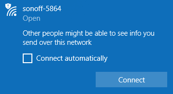
So after the jumpers are placed properly, you can turn on the device with the AC supply, After few seconds a device will host Acces point with the name Armtronix or sonoff followed by last four digits representing mac address as shown in Image 8.
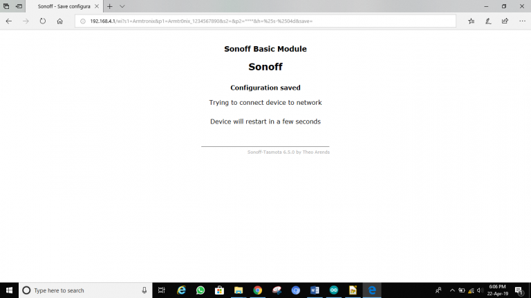
So once you connect to the Access point, open the browser and type 192.168.4.1, the page will be loaded for configuration as shown in Image 9.
After entering the required SSID and password click on the save button, once save button is pressed you will see the changes as in Image 10.
Step 6:


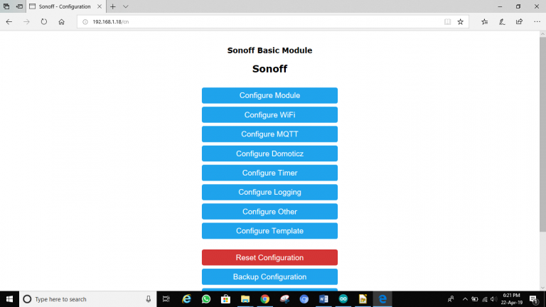
Once the device is configured, you must find the IP address of the device by logging into your router or you can use fing app, once you know the IP address, enter it in your browser connected to the same network to which you had configured the device earlier and you will get as same as in Image 11.
Finally you have to configure the device module by clicking on configuration button (Image 12).
And then in configure module Select ARMTR Dimmer (56) from the dropdown menu and click on save (Image 13) and the device restarts (Image 14). And its Done!!!


