

Introduction: Super Simple Electrocardiogram (ECG) Circuit


Electrocardiography is the study of the electrical signals produced by the heart during the cardiac cycle. Doctors monitor a person's electrocardiogram (ECG) in order to assess how the heart is functioning and can be used to diagnose a variety of cardiac diseases. The ECG is thought to have first been discovered by Alexander Muirhead[1] and has become a hallmark in patient care. It turns out that an ECG is very easily obtained with a few common circuit components. I'll show you how to build a "Super Simply Electrocardiogram (ECG) Circuit."
This Instructable assumes that you know a few basic concepts of circuit design and analysis such as:
Nodal Analysis
Operational Amplifiers
Filters
If you are a bit shaky on these topics, please consult the links provided for additional information.
[1] "Electrocardiography." Accessed: November 5, 2016. <https://en.wikipedia.org/wiki/Electrocardiography>
Warning: Please do not connect your ECG circuit to a wall outlet or any instrument powered through the wall outlet for safety reasons.
Warning: This is not a medical device.
Step 1: Gather Your Tools
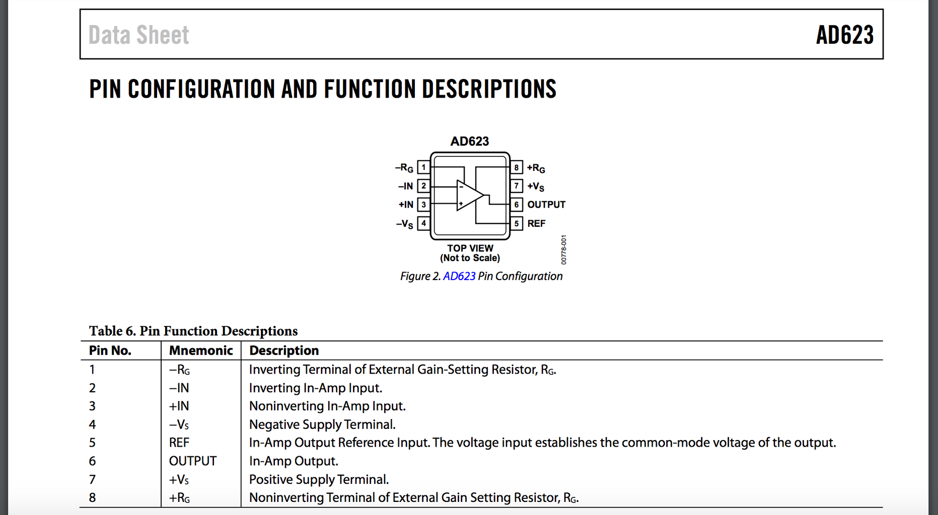
Instrumentation Amplifier
1 x AD623
Resistor
1 x 1k
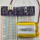
Power Supplies
+5V
-5V
(2 lithium polymer batteries are suggested. That would give you +/- 3.7V.)
Warning: Please do not connect your ECG circuit to a wall outlet or any instrument powered through the wall outlet for safety reasons.
Accessories
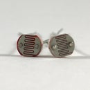
3 x ECG electrodes
3 x Test leads
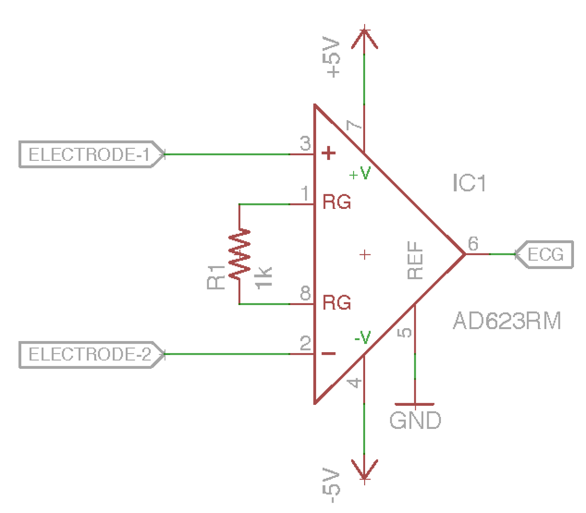
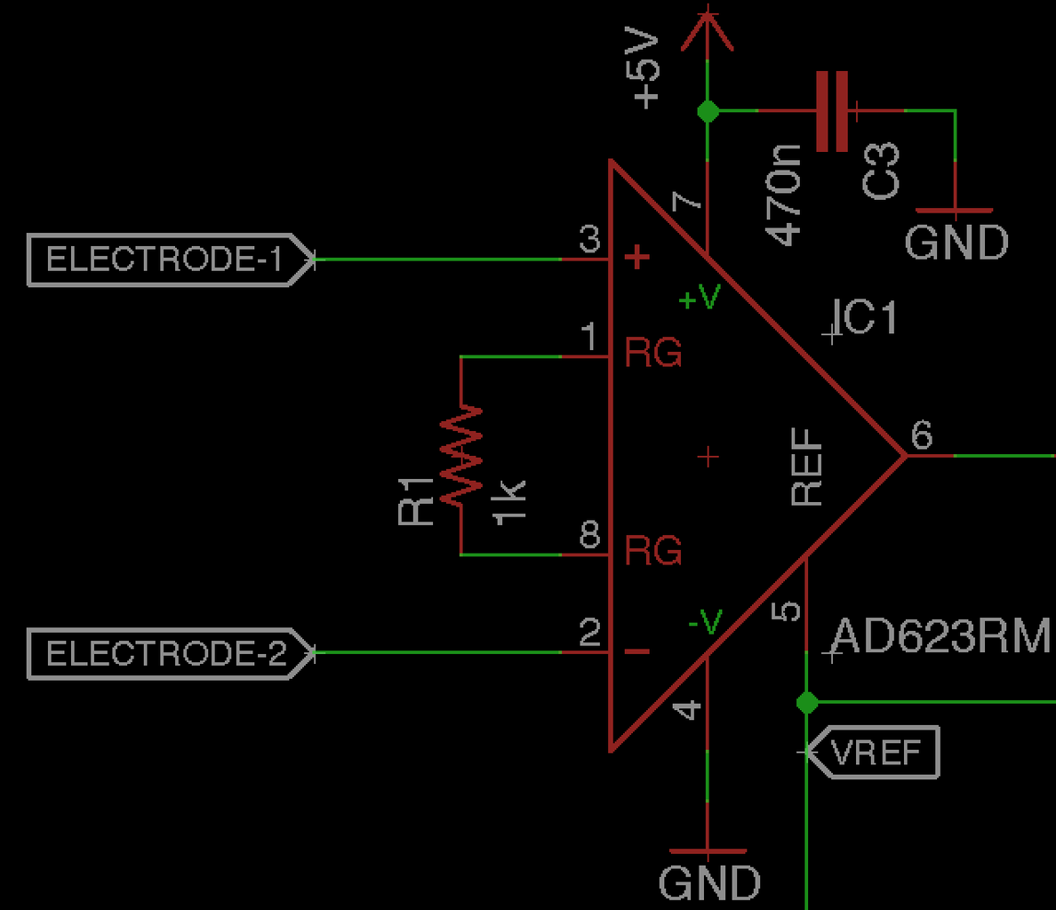
Step 2: Instrumentation Amplifier


The Instrumentation Amplifier is probably the hallmark amplifier for bioelectrical measurements for a number of reasons, most notably: (1) high input impedance and (2) very good common mode rejection. High input impedance ensures that we do not draw current from the system that we are measuring. Since we are connected to a biological system, drawing current from that system can actually be dangerous in some instances. Additionally, electrodes are often used to interface the biological system with the circuit. We usually use metals as electrodes, which are very good conductors of electricity. Unfortunately, the impedance of an electrode can vary unpredictably when placed into a biological system for a number of reasons. Using a high input impedance amplifier helps us nullify the effects of changing electrode impedance and maintain signal integrity.
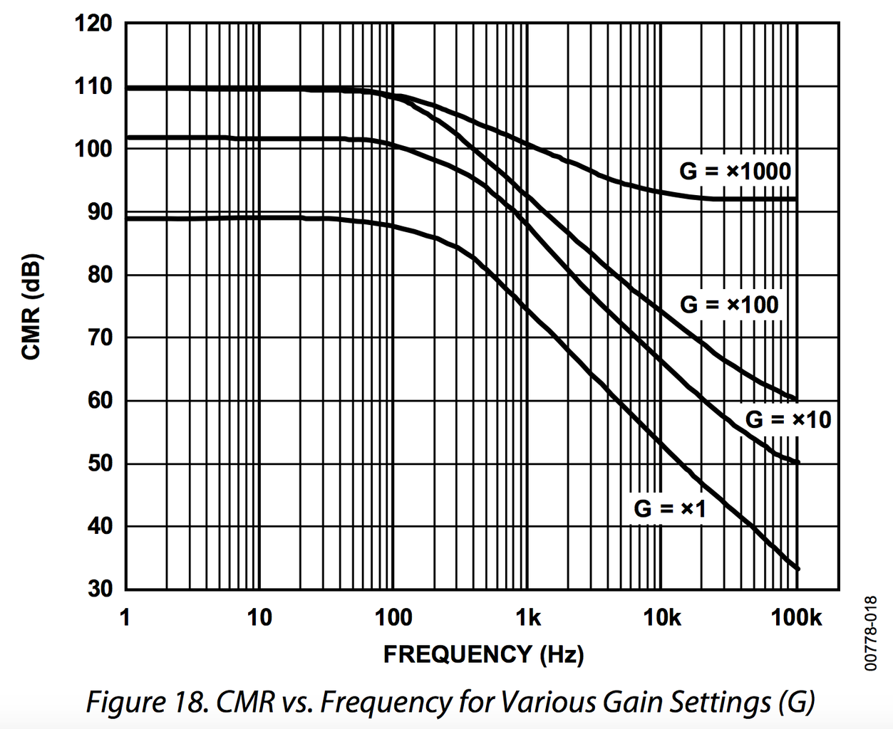
Common mode rejection allows us to diminish the effects of background signals that distort our measurement, often called common mode noise. Instrumentation amplifiers are specifically designed to ensure we reject as much common-mode noise as we can. This parameter is reported in the amplifier's "datasheet" which is essentially the amplifier's spec sheet produced by the manufacturer of the device. You will typically find CMRR (Common Mode Rejection Ratio) or CMR (Common Mode Rejection) reported as a function of frequency and is given in units of "dB." dB stands for "decibels" and is a logarithmic relationship of voltage gain.
CMRR and decibels are a bit out of the scope of this Instructable. Please see the links for more information.
Step 3: Electrode Connections and Powering the Amplifier


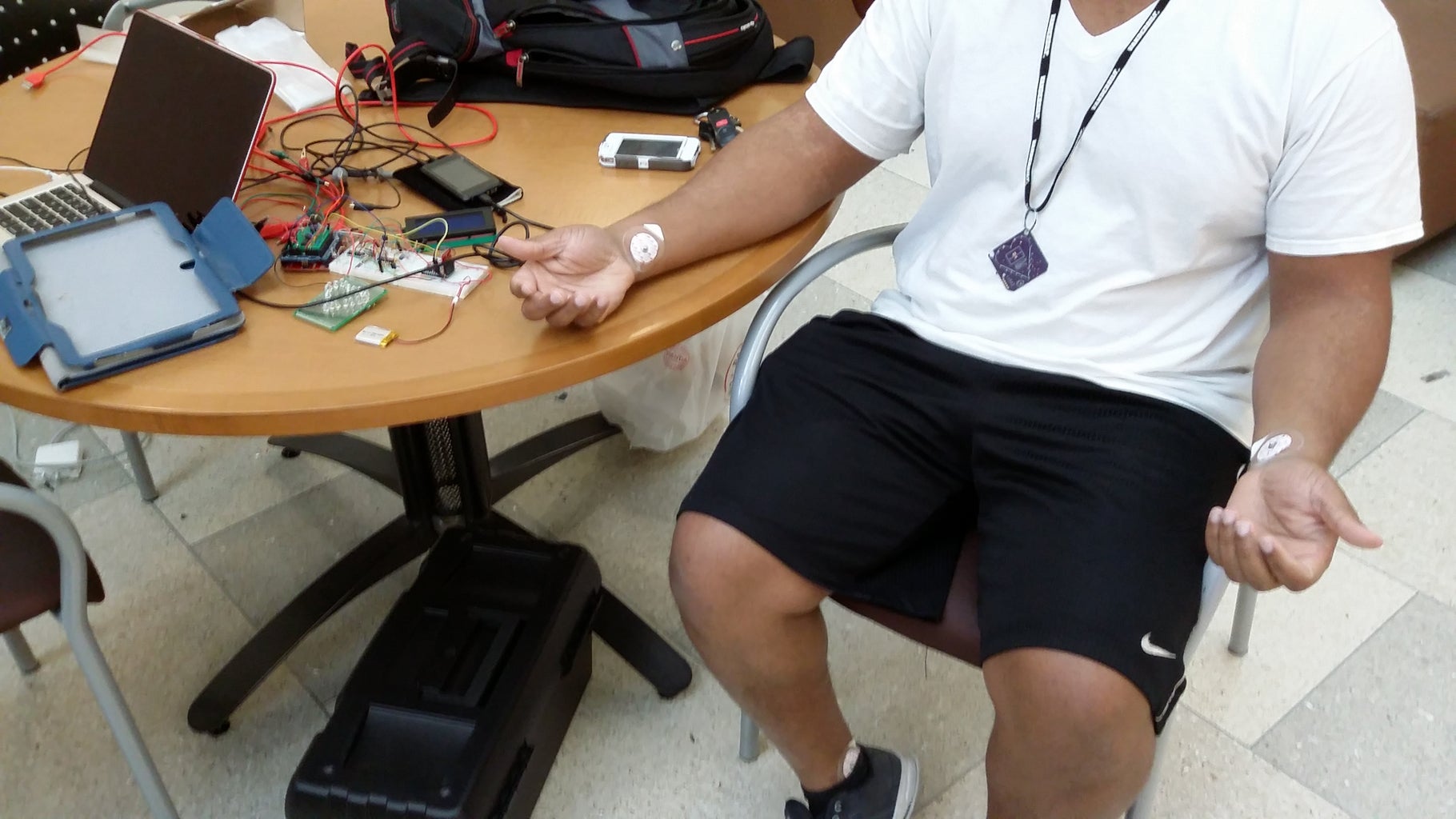
There are many places on the body to put your electrodes to record the ECG. For this demo, I placed electrodes on my right wrist, my left wrist, and my right ankle. The right wrist electrode is "Electrode 1." The left wrist electrode is "Electrode 2." The right ankle electrode is attached to ground.
Additionally, power the op amp by placing +5V at "+Vs" (pin 6) and -5V at "-Vs" (pin 4).
Step 4: That's It!

For the most part, that's all you need. The rest of this tutorial adds a few components based upon how you decide to configure your instrumentation amplifier.
Step 5: Gather Your Tools
For the rest of this Instructable, I will use a modified circuit to use a "single supply" with my amplifiers. We need a few more components.
Instrumentation Amplifier
1 x AD623
Op Amps
1 x MCP6002
Resistors
1 x 1k
1 x 10k
1 x 820k
1 x 1.47M
Capacitors
3 x 470nF
Power Supplies
+5V
(1 lithium polymer battery is suggested. That would give you +3.7V. I powered mine through 5V on the Arduino, however, with my Arduino disconnected from mains.)
Warning: Please do not connect your ECG circuit to a wall outlet or any instrument powered through the wall outlet for safety reasons.
Accessories
3 x ECG electrodes
3 x Test leads
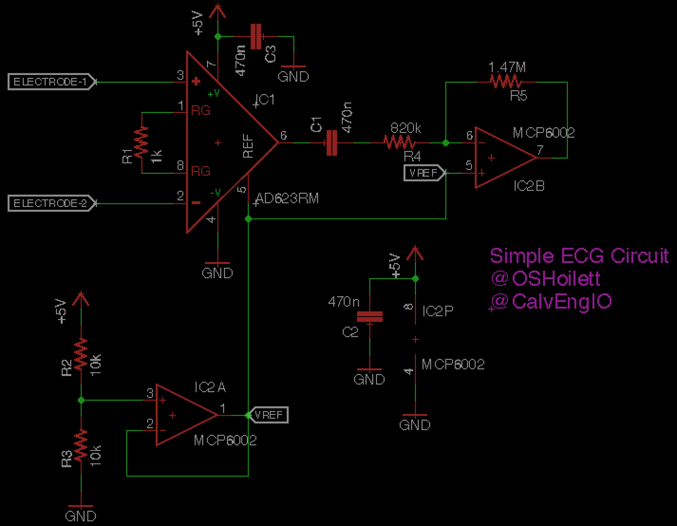
Step 6: Modifying Our Instrumentation Amplifier With a Vref Generator


I often use "single supply" amplifiers for convenience. Many amplifiers are powered with a "bi-polar supply" meaning that you have to give the amplifier a positive and a negative voltage for it to operate correctly. Some amplifiers are specified for "single supply" operation meaning you only need a positive voltage and ground to operate the amplifier. This is really convenient because it allows us to operate amplifiers with very small batteries such as lithium polymer battery (3.7 V) or even a few AAA batteries (1.5 V). Single supply operation is even more convenient when using a microcontroller with our amplifiers. Microcontrollers most often work with a single voltage supply (for example, the Arduino UNO runs off 5 V).
Single supply operation poses a bit of a problem, however, for using our instrumentation amplifier for measuring ECG. Our ECG waveform is AC (alternating current) and will alternate between positive and negative voltages. As a result, we will use a Vref (voltage reference) generator, that will provide an offset voltage for the output of our instrumentation amplifier. This ensures that the output voltage of the instrumentation amplifier will never be negative. We will set our Vref generator to 1/2 of the positive supply voltage. In my case, I powered by circuit with 5V. My Vref generator is then 2.5V.
Step 7: Electrode Connections and Powering the Amplifier


Electrode connections are the same as Step 3 except for the right ankle electrode which is now attached to Vref instead of Ground (0 V). Otherwise, the right wrist electrode is "Electrode 1" and the left wrist electrode is "Electrode 2."
However, the power connections for our amplifier change slightly. Power the op amp by placing +5V at "+Vs" (pin 6) and Ground at "-Vs" (pin 4). Also, place the output of the Vref generator at "REF" (pin 5).
Step 8: Additional Gain Stage: Active Highpass Filter

You may find that your signal is not big enough, even after putting a bit of gain on the instrumentation amplifier. If you do, an additional amplifier circuit will do the trick. Any number of amplifier configurations will work, but for reference sake I used an inverting amplifier. Notice from the diagram, we are also doing a bit of filtering in this stage as well, making this stage an "active highpass filter."
You may notice a few deviations from the typical inverting amplifier configuration that you may be familiar with. First, instead of placing a ground at the non-inverting pin, we actually place our generated reference voltage from step 6. Secondly, we include a high pass filter at the input of our inverting amplifier. This filter has a pretty specific purpose. Even though we used a Vref generator for our instrumentation amplifier to ensure that our output is maintained at a specific voltage level, small deviations from this level can occur. (Reasons for the deviations will be explained in Step 10). As such we use a high pass filter to block the unstable voltage level and re-center the signal at our generated reference voltage. Recall from op amp rules that the voltage at the inputs of our op amp are equal. Therefore, if the voltage at the non-inverting pin is Vref, then the voltage at the inverting pin is also Vref. Furthermore, because we use a high pass filter at the input of the amplifier, there will be no DC gain by our inverting amplifier and our output voltage will also be centered around Vref.
Step 9: That's It! (Again)

You're done! No matter how many times I do this project (and it's a lot), I still get a kick out of it. It think it's pretty cool. Anyways, until next time. Enjoy!
Step 10: A Few Pitfalls
The above video demonstrates what my ECG signal looked like when a number of the following guidelines were not followed.
Electrode connections
- Electrode placement and contact is essential for obtaining a stable ECG signal. Please ensure that your electrodes have very good contact with the skin and are not drying out. Please use electrode gel to ensure your electrodes remain moist.
- We usually pick up small DC voltages with our electrodes that will subsequently be amplified by our Instrumentation amplifier. If you notice that the output of your instrumentation amplifier goes to the maximum or minimum voltage, please decrease the gain of the amplifier. You can also check the DC offset voltage on your electrodes by measuring the DC voltage at each of inputs of the instrumentation amplifier. If the difference in the DC voltage of each of your inputs multiplied by the gain of your amplifier is very large, then your signal is will be distorted by causing a strong deviation from our bias point that we set in Step 3. Try adjusting the electrodes to ensure firm contact with your skin and/or apply electrode gel to ensure a good connection.
Amplifier Considerations
- I have noticed that any resistance smaller than 1k for Rg causes unstable behavior in the amplifier.
Power-on Sequence
- I suggest connecting all your electrodes to your circuit, including ground, before turning your circuit on. If the inputs of your instrumentation amplifier are not connected to a reference point before the amplifier is turned on, they could "float" unpredictably causing the output of your amplifier to be unstable. Immediately connecting your electrodes may not solve this problem as the amplifier has to re-adjust quickly and may not have a proper path to discharge the its output.
General Guidelines
- Stay still. Moving around will distort your signal.
- Stay relaxed. Tensing your muscles will causes distortion by picking up electrical signals from skeletal muscles instead of the heart.
A Few More Suggestions
Gain and more Filtering
- I made this circuit for general biopotential measurements, but once you figure out the specific signal you want to measure, you'll probably need to make more changes. For ECG, the amount of gain used is probably sufficient, but for EEG or a more sensitive signal, you'll probably need some more gain. I would recommend adding a few bandpass filters. I usually use two bandpass filters with gains of 26.6dB and cutoff frequencies of 0.7Hz and 34Hz for EEG.
- A 60Hz notch filter would be nice as well.
Step 11: Going on Further
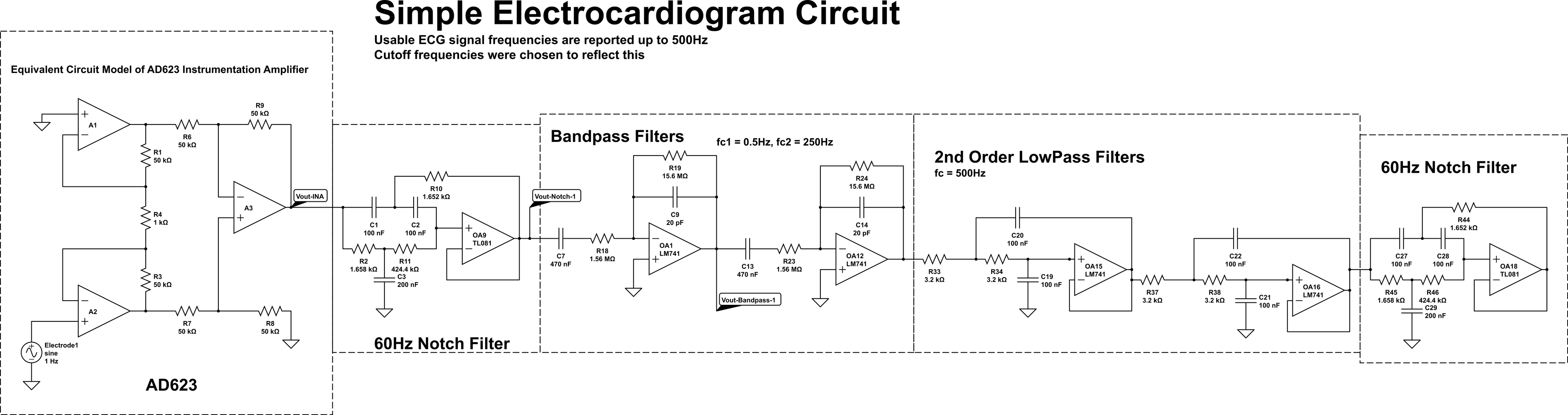

There is MUCH, MUCH more we can do to this circuit to make it robust. The purpose of this Instructable was to provide the minimal circuitry necessary to obtain a reasonable ECG signal. I have presented the circuit I used to do just that. I attached screenshots of a mock-up of a more involved circuit design. Please note that this design was simulated and not built. I have also included the magnitude vs. frequency response of the circuit.You can modify the simulation on Circuitlab.com. Please feel free to search the web for more sophisticated implementations of the ECG circuit, but what I have presented should get you going. Have fun!

Participated in the
Circuits Contest 2016


