

Introduction: Arduino Distance Measuring Device in a Easy Way
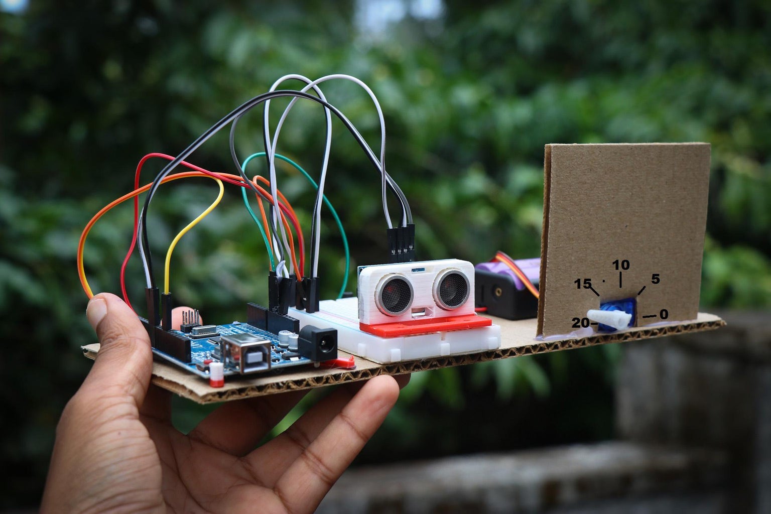


Hello learners in this instructable i will show you how you can make your very own arduino scale or you can call it as a measuring device that can measure the distance of the objects in front of it and show the numbers with the pointers.
If you want to learn arduino i would highly recommend building this project since you will get a chance to have hand on experience in working with different modules of Arduino along with program and circuit diagrams.
This is not just a project from the other point of view it will help a lot in understanding the arduino and its setup with micro servo and ultrasonic sensor.
The simple components are connected together and used as a scale, The principle behind its working is simple the ultrasonic sensor sends signals from one side(transmitter) and receives the signal from another side(receiver).
When this is happening if any obstacle comes in front of the sensor the signals get deflected and this time is noted down and the same is represented by the horns of the servo.
This simple logic is put up in a creative manner to make this work as a scale, If you want to learn arduino i would highly recommend building this project since you will get a chance to have hand on experience in working with different modules of Arduino along with program and circuit diagram.
I have included all the circuits and codes necessary for this project, also there is a video in the end to help you make understand better. All the best for your project :)
Supplies
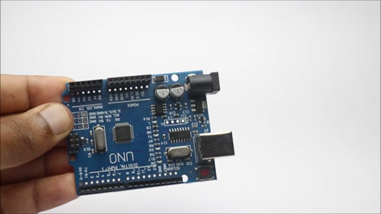


Arduino Uno
Ultrasonic Sensor
Micro Servo
Jumper Wires
All in one kit to build this Project
3d printed case for ultrasonic sensor(optional)
Breadboard (small is enough)
Pieces of cardboard
Hot glue
Scissors
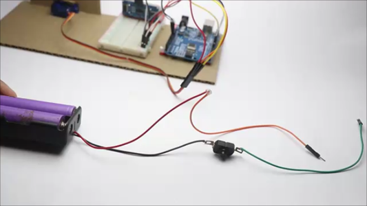
Battery and holder
Small switch
Step 1: Circuit Diagram


The favourite part of mine is building the circuit, This circuit is very simple to make and i will explain how you can make this in no time.
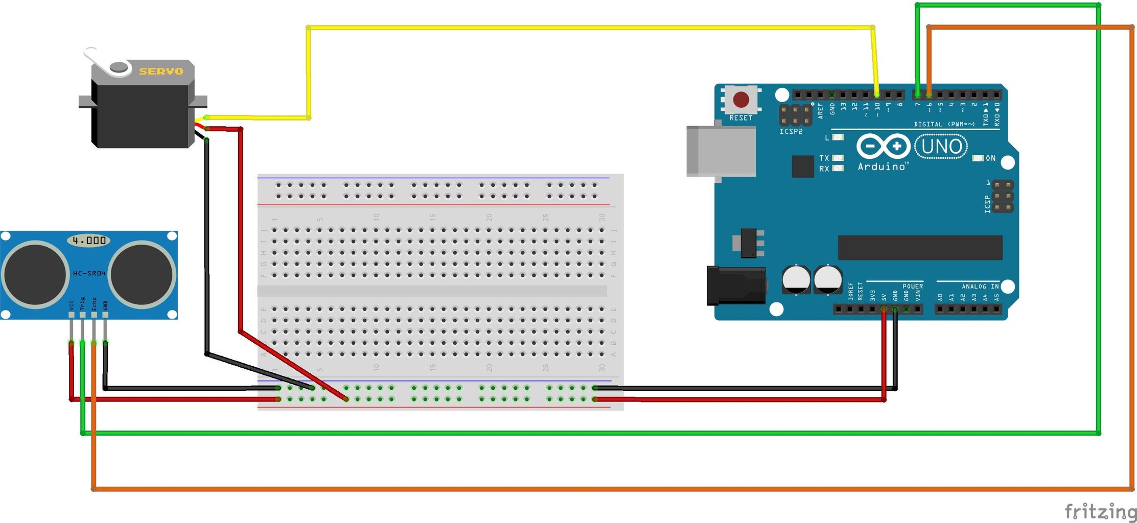
The circuit can be divided into 2 steps, the first is the hcsr04 part circuit and the second is the micro servo circuitry.
The Hc-Sr04 or called as ultrasonic sensor comes with 4 pins, Here the Gnd and Vcc pins are directly connected to the Gnd and 5v pin on the Uno board.
The Trig and Echo pins are connected to the D7 and D6 pins of the uno board, Here I have connected both of these pins to the uno board directly while the rest 2 pins are connected to the power rails of the breadboard.
Let us connect the servo too, The servo has 3 pins, The signal, the positive and the negative.
Connect the signal pin directly to the D10 pin of the uno board where as the power pins will be connected to the power rails on the breadboard.
Use jumper wires to establish the connection between all these components, After this is complete we will upload codes to the uno board.
You also can simplify this circuit with a Single PCB, Complete your electronic projects in the best way from PCBWay
They are raining shipping discounts for assembled orders click here to get your discount offer.
Why them? They have provided me with the best PCB and The quality is just amazing compared to other providers in the market
Check Here for Rigid-flex Pcbs with this your circuit becomes flexible! I have added the images to this step kindly check.
A revolutionary solution that combines the best of both rigid and flexible circuitry to elevate your electronic projects to new heights.
You should not miss their PCB prototype assembly where you can get high quality assembled PCB
With their expertise in advanced manufacturing techniques, they offer a seamless integration of rigid and flexible components, ensuring enhanced reliability, durability, and space-saving benefits
Step 2: Arduino Code

The arduino code used in this project is very easy to understand, I have dropped the code file below.
Open the code and copy it to the clipboard of the computer, Now open the IDE and paste this code.
You can also change various parameters like the delay time to activate the servo, the movements, and the distance, For this project I have made the best possible adjustments, and if you think I missed anything you can let me know in the comments.
Connect the Uno board to the computer and select the type of board from the setting menu in IDE, Make sure the ports are selected properly and click on the upload button.
It will take some time to upload the code to the board, Now to make sure if the code is working fine all you have to do is place your hand in front of the ultrasonic sensor.
As you move the object away from the sensor the servo horn should fluctuate and if this happens everything is set, Note that you have to use half servo horn and that should be placed at a flat angle as i did.
Now we will assemble all these electronics on a board to make it look like a device.
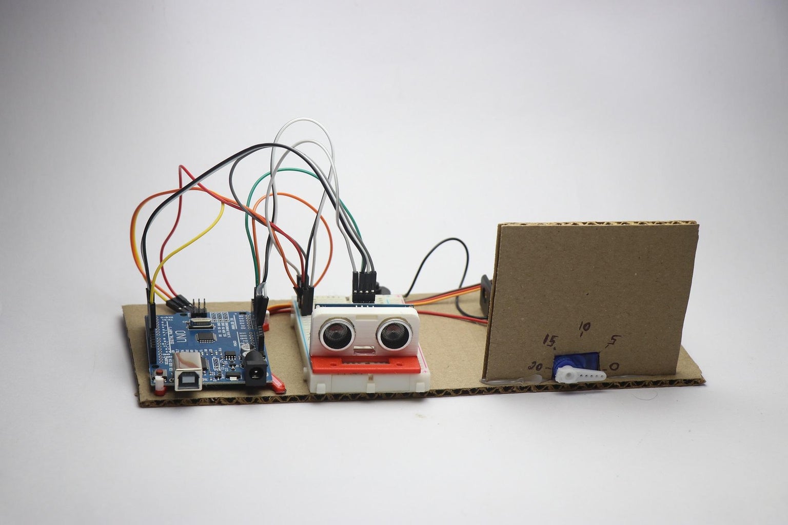
Step 3: Assembling


Coming to this part there are other alternatives like using the 3d printed parts and a full enclosure, But I found using the cardboard board does the job and it looks great too.
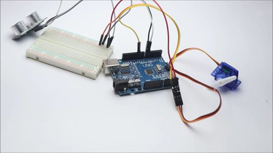
Place the arduino uno on the board followed by the breadboard and servo, and use a tiny amount of hot glue to glue all these components to the board.
To make the servo holder, cut a square piece of cardboard and to the base taking reference of servo cut a small slot, Glue the holder to the cardboard base, and allow it until it is dry.
I added a little extra touch by casing the ultrasonic sensor with a 3d printed part, This is an optional step and if you don't have a case you can simply glue it to the baseboard or breadboard.
Here you should make a note that the sensor is glued to the side and no obstacle should be there in front of the board.
Step 4: How to Use

Using this project is very simple, Turn on the power button given at the backside of the board and make sure there is no obstacle placed in front of the sensor.
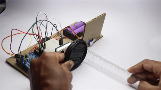
For your reference in the beginning you have to place a ruler and keep any obstacles in front of the sensor, note down the readings, and mark the measurements on the meter.
After a few attempts the servo becomes stable and will start to show the accurate readings, note that the limit here is 20cms and above this, the servo starts to jitter.
This completes our project and by now you should be measuring the small distances with this project! Note that this is just a prototype to show the abilities of arduino, you cant use this project to take measurements like a precise scale, but this does the job.
That's all about this arduino measuring device, watch the video given in the next step to see how this works.
Step 5: Working Video of Arduino Scale
Instead of calling this a measuring device I will call this as a scale, In this video tutorial you can watch the making video and also learn how to use this scale.
There are lots of customization options for this project, all you have to do is explore the arduino program.
That is all about this project, if you have any questions you can drop comments and i will respond to all your queries.

Participated in the
Anything Goes Contest

![Tim's Mechanical Spider Leg [LU9685-20CU]](https://content.instructables.com/FFB/5R4I/LVKZ6G6R/FFB5R4ILVKZ6G6R.png?auto=webp&crop=1.2%3A1&frame=1&width=306)


