

Introduction: Arduino Timers: 8 Projects


The Arduino Uno or Nano can generate accurate digital signals on six dedicated pins by using the three built-in timers. They only require a few commands to set up and use no CPU cycles to run!
Using the timers can be intimidating if you start from the ATMEGA328 full datasheet, which has 90 pages dedicated to their description! Several built-in Arduino commands already use the timers, for example millis(), delay(), tone(), AnalogWrite() and the servo library. But to use their full power, you’ll need to set them up through the registers. I share here some macros and functions to make this easier and more transparent.
After a very brief overview of the timers, follow 8 cool projects that rely on signal generation with the timers.
Step 1: Required Components
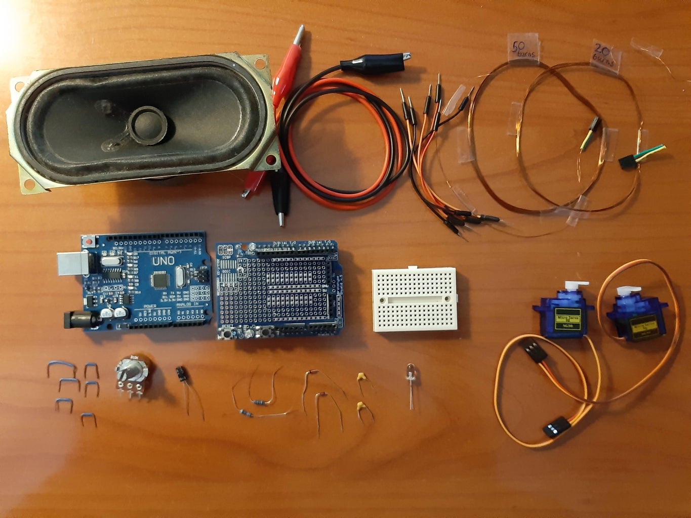
To make all 8 projects you'll need:
- An Arduino Uno or compatible
- A prototype shield with mini protoboard
- 6 breadboard jumper cables
- 6 short breadboard jumpers (make yourself from 10cm solid core hookup wire)
- 2 crocodile leads
- 1 white 5mm LED
- a 220 Ohm resistor
- a 10kOhm resistor
- a 10kOhm potentiometer
- 2 ceramic 1muF capacitors
- 1 electrolytic 10muF capacitor
- 2 diodes, 1n4148 or similar
- 2 micro servo motors SG90
- 1 8Ohm speaker
- 20m of thin (0.13mm) enameled wire
Step 2: Overview of the Arduino Timers for Signal Generation
Timer0 and timer2 are 8-bit timers, meaning that they can count from 0 to 255 at most. Timer1 is a 16-bit timer, so it can count up to 65535. Each timer has two associated output pins: 6 and 5 for timer0, 9 and 10 for timer1, 11 and 3 for timer2. The timer gets incremented at each Arduino clock cycle, or at a rate that is reduced by a prescale factor, which is either 8, 64, 256 or 1024 (32 and 128 are also allowed for timer2). The timers count from 0 to ‘TOP’ and then over again (fast PWM) or downward (phase correct PWM). The value of ‘TOP’ thus determines the frequency. The output pins can set, reset, or flip at the value of the Output Compare Register, so those determine the duty cycle. Only timer1 has the ability to independently set the frequency and the duty cycles for both output pins.
Step 3: LED Blink
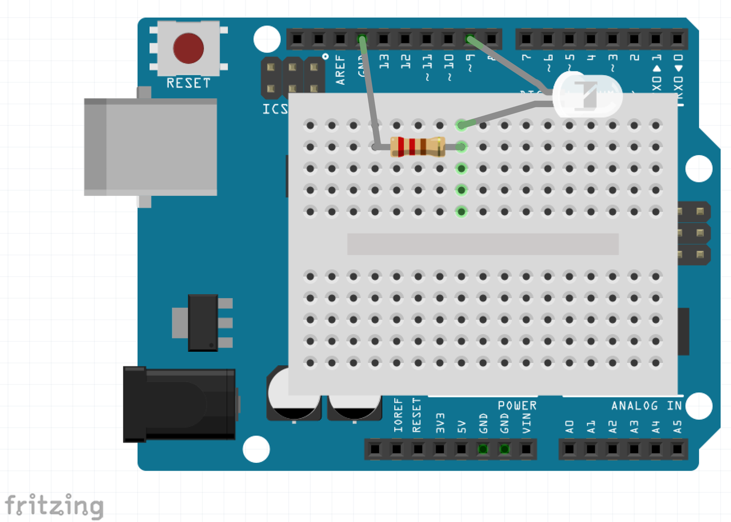
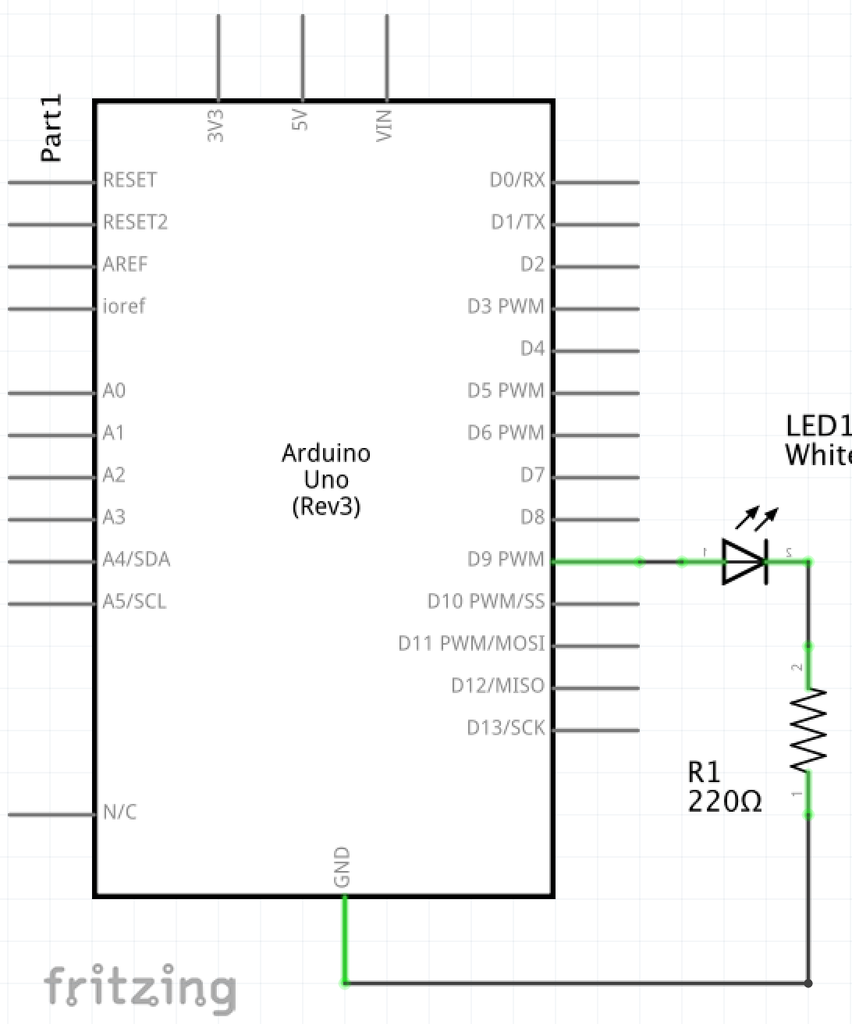
The lowest frequency that can be reached with the 8-bit timers is 16MHz/(511*1024)=30,6Hz. So to make a LED blink with 1Hz, we need timer1, which can reach frequencies 256 times smaller, 0.12 Hz.
Connect a LED with its anode (long leg) to pin9 and connect its cathode with a 220 Ohm resistor to ground. Upload the code. The LED will blink at exactly 1Hz with a duty cycle of 50%. The loop() function is empty: the timer is initialized at setup() and does not need any further attention.
Attachments

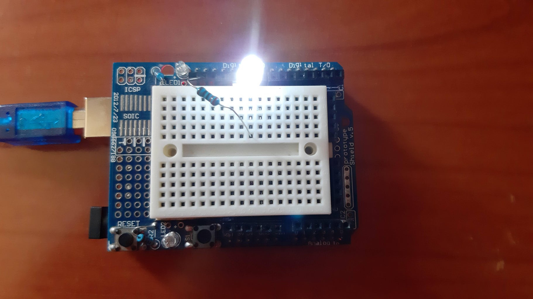
Step 4: LED Dimmer
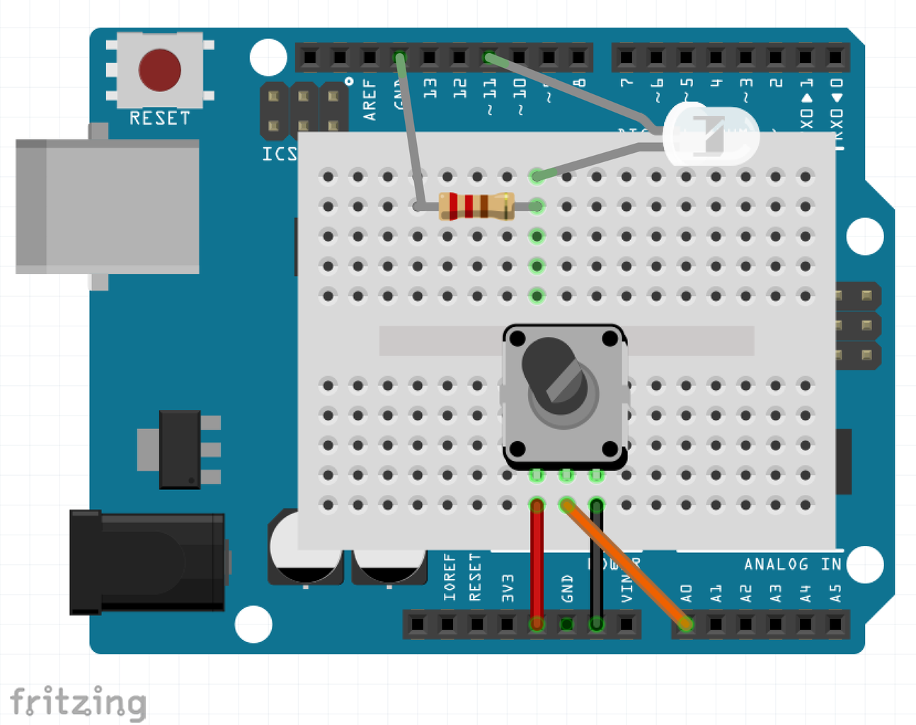
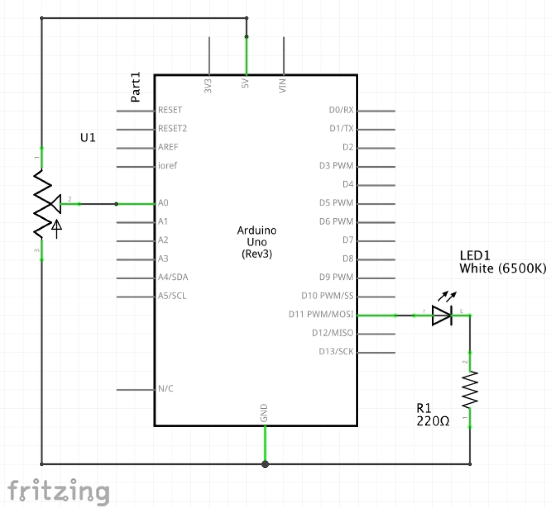

Pulse-width modulation is an effective way to regulate the intensity of an LED. With a proper driver, it is also the preferred method to regulate the speed of electromotors. Since the signal is either 100% on or 100% off, no power is wasted on a series resistance. Basically, it’s like flashing the LED faster than the eye can follow. 50Hz is in principle sufficient, but it it may still seem to flicker a bit and when the LED or the eyes move, an annoying non-continuous ‘trail’ may result. Using a prescale of 64 with an 8-bit timer, we get 16MHz/(64*256)=977Hz, which suits the purpose. We pick timer2, so that timer1 remains available for other functions, and we don’t interfere with the Arduino time() function, which uses timer0.
In this example the duty cycle, and thus the intensity, is regulated by a potentiometer. A second LED can be regulated independently with the same timer at pin 3.
Attachments
Step 5: Digital-to-Analog Converter (DAC)
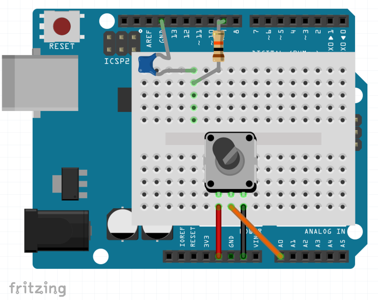
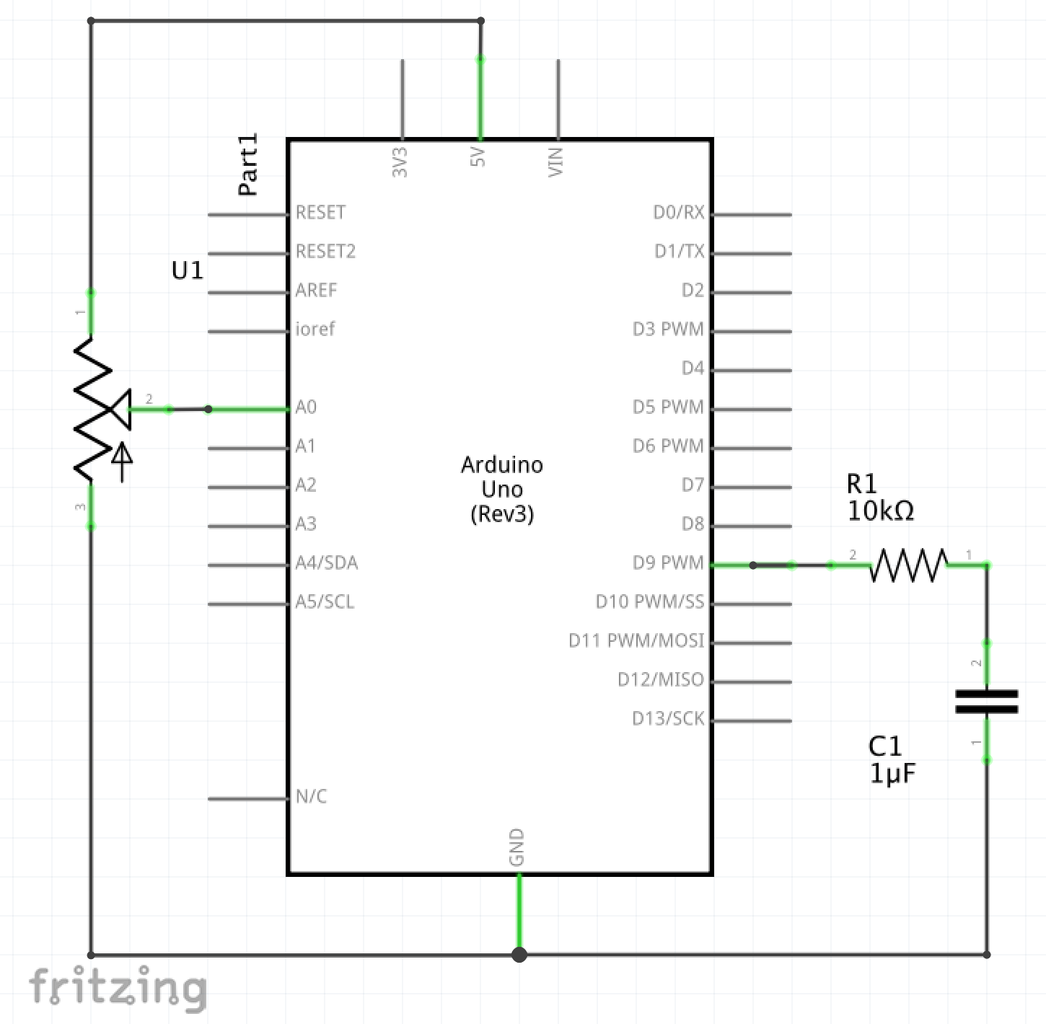

The Arduino does not have a true analog output. Some modules take an analog voltage to regulate a parameter (display contrast, detection threshold etc). With just one capacitor and resistor, timer1 can be used to create an analog voltage with a resolution of 5mV or better.
A low-pass filter can ‘average’ the PWM signal to an analog voltage. A capacitor is connected through a resistor to a PWM pin. The characteristics are determined by the PWM frequency and the values of the resistor and capacitor. The resolution of the 8-bit timers would be 5V/256=20mV, so we opt for Timer1 to get 10-bit resolution. The RC circuit is a first-order low-pass filter and it will have some ripple. The time-scale of the RC circuit should be much larger than the period of the PWM signal to reduce the ripple. The period we get for a 10-bit precision is 1024/16MHz= 64mus. If we use a 1muF capacitor and a 10kOhm resistor, RC=10ms. The peak-to-peak ripple is at most 5V*0.5*T/(RC)=16mV, which is considered sufficient here.
Note that this DAC has a very high output impedance (10kOhm), so the voltage will drop significantly if it draws current. To avoid that, it can be buffered with an opamp, or another combination of R and C can be chosen, for example 1kOhm with 10muF.
In the example, the DAC output is steered with a potentiometer. A second independent DAC channel can be run with timer1 on pin 10.
Attachments
Step 6: Metronome
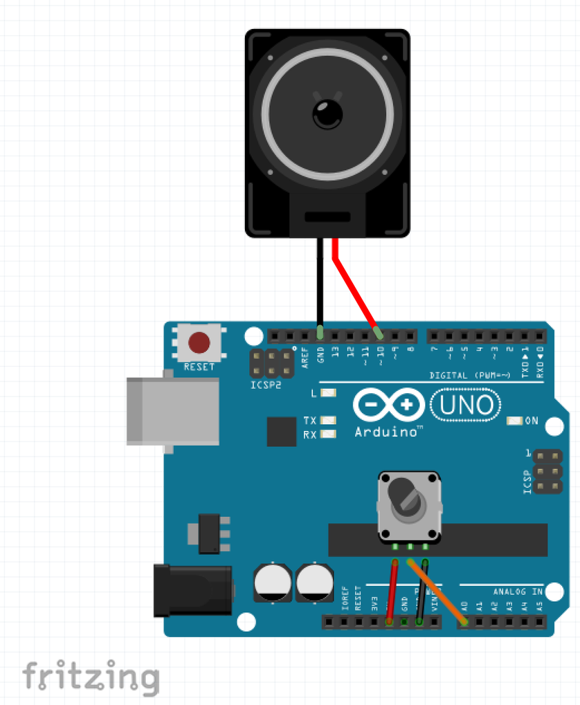
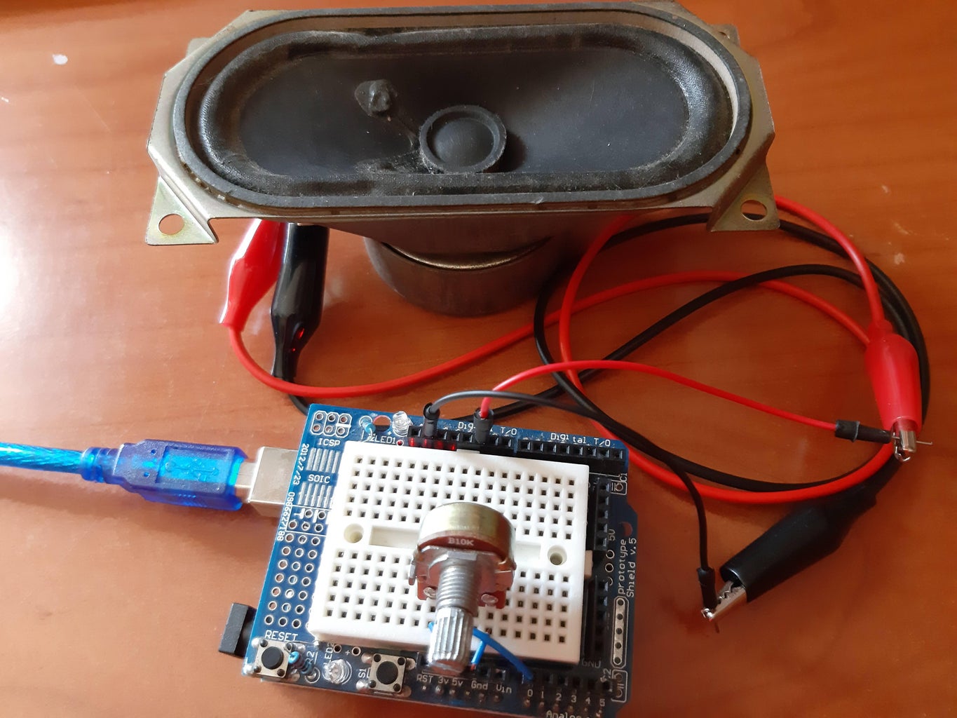
A metronome helps to keep track of the rhythm when playing music. For very short pulses, the arduino timer output can be fed directly to a speaker, which will produce clearly audible clicks. With a potentiometer, the beat frequency can be regulated from 40 to 208 beats per minute, in 39 steps. Timer1 is needed for the required precision. The value of ‘TOP’, which determines the frequency, is modified inside the loop() function, and that requires attention! You see here that the WGM mode differs from the other examples that have fixed frequency: this mode, with TOP set by the OCR1A register, has double buffering and protects against missing TOP and getting a long glitch. However, this means we can use only 1 output pin.
Attachments
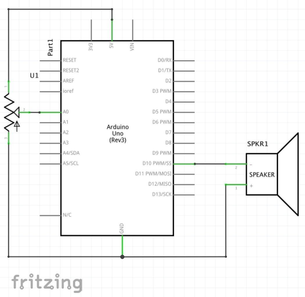
Step 7: Sound Spectrum
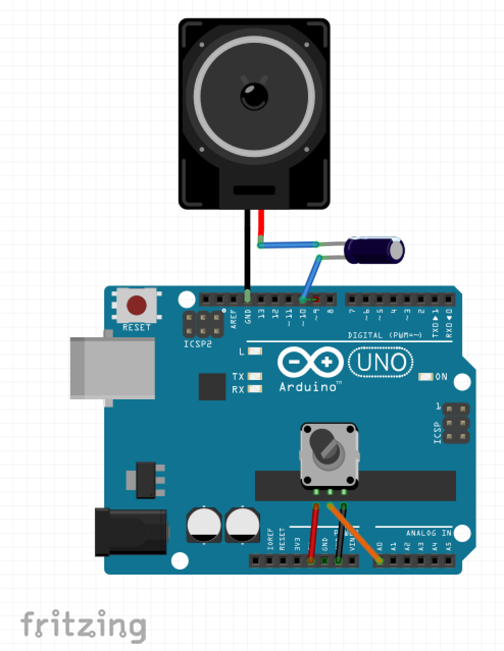
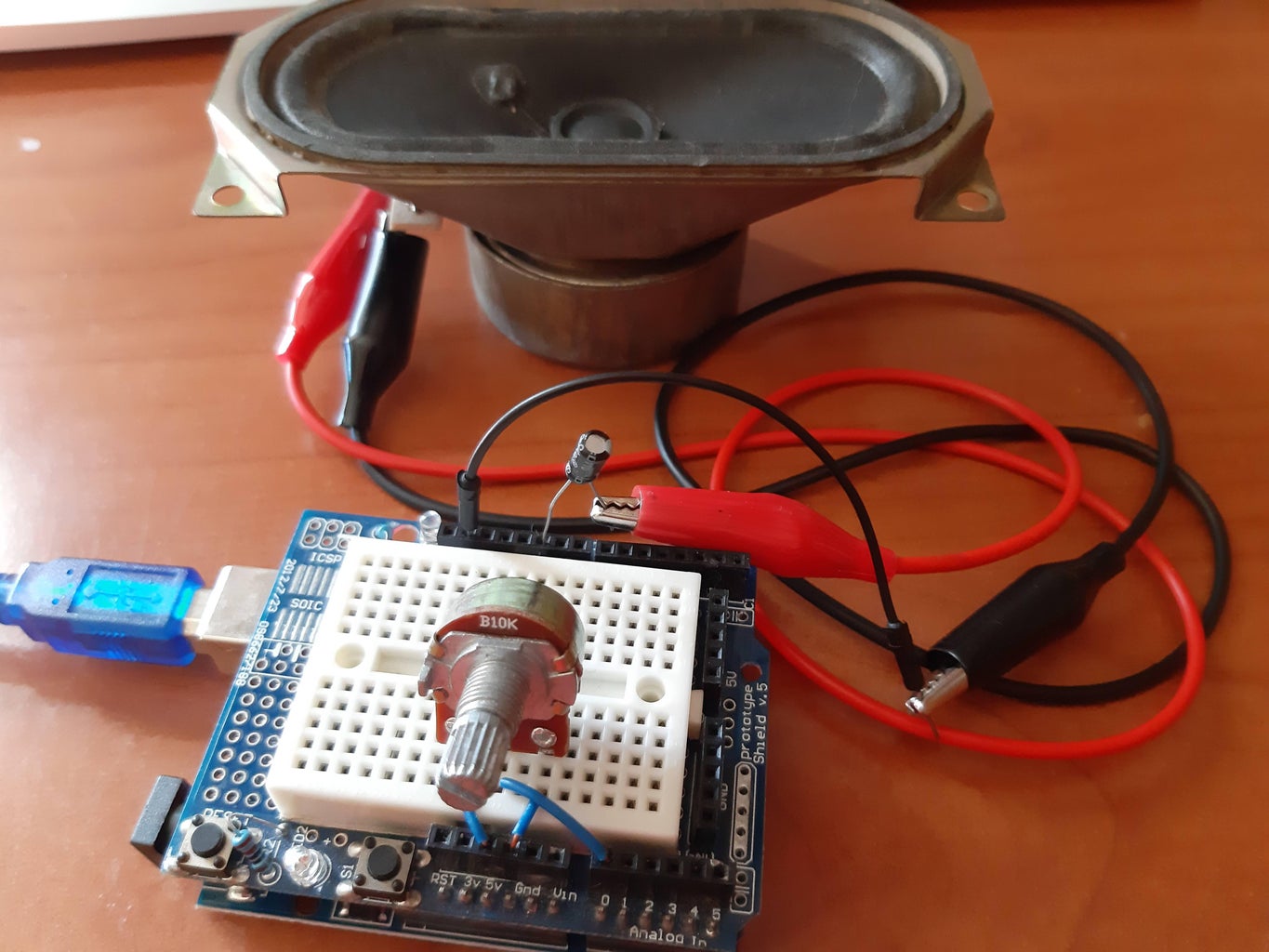

Humans can hear over 3 orders of magnitude of sound frequencies, from 20Hz to 20kHz This example generates the full spectrum with a potentiometer. A 10muF capacitor is put between the speaker and the Arduino to block the DC current. Timer1 produces a square wave. The Waveform generation mode here is Phase-correct PWM. In that mode, the counter starts counting backward when it reaches top, which results in pulses that have their mean fixed, even when the duty cycle varies. However, it also results in a period that is (almost) double, and it just happens that with prescale 8, timer1 covers the full audible spectrum, without the needing to change prescale. Also here, since the value of TOP is being changed on-the-go, using OCR1A as top reduces glitches.
Attachments
Step 8: Servo Motors
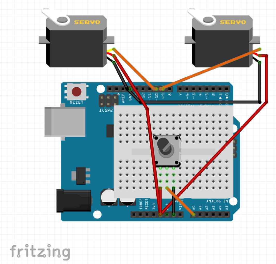
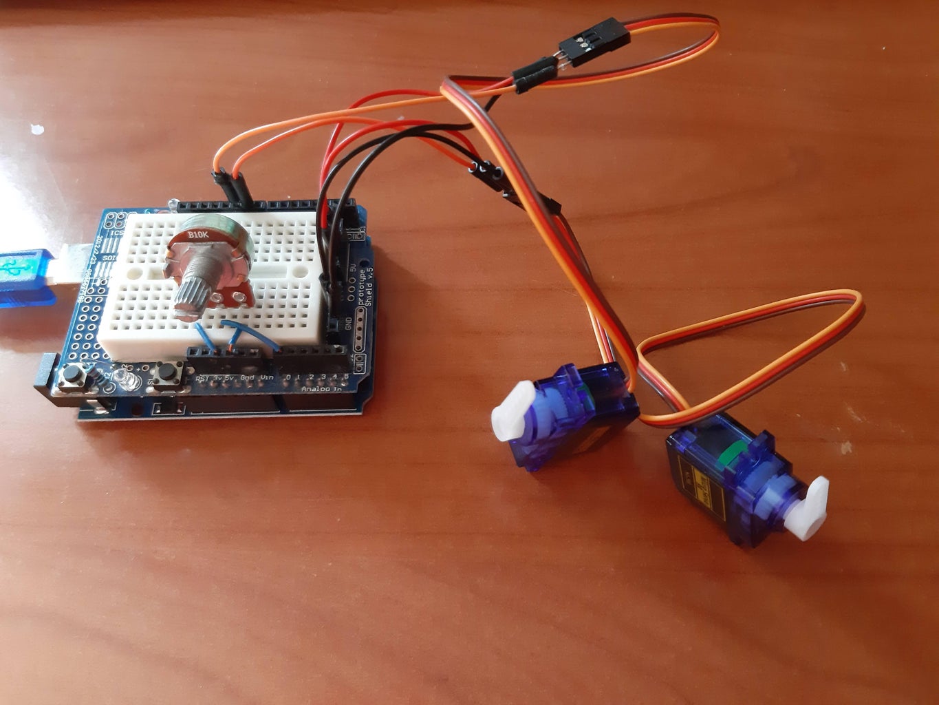
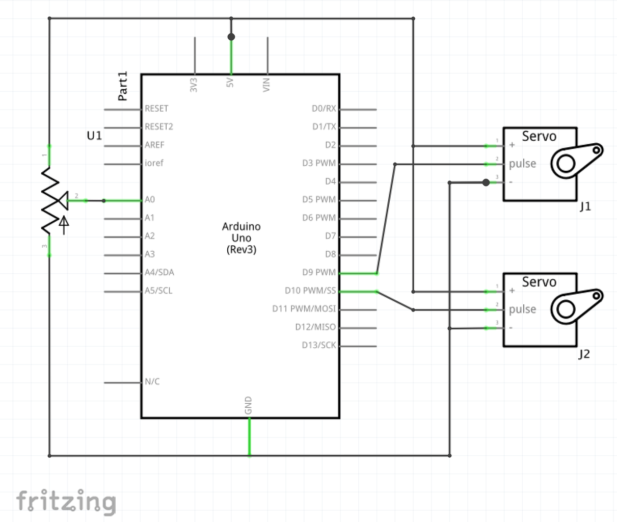
There are powerful servo libraries, but if you have only two servos to drive, you might as well do it directly with timer1, and thus reduce CPU, memory use, and avoid interrupts. The popular SG90 servo takes a 50Hz signal, and the pulse length codes the position. Ideal for timer1. The frequency is fixed, so both outputs on pin9 and pin 10 can be used to steer the servos independently.
Attachments
Step 9: Voltage Doubler and Inverter
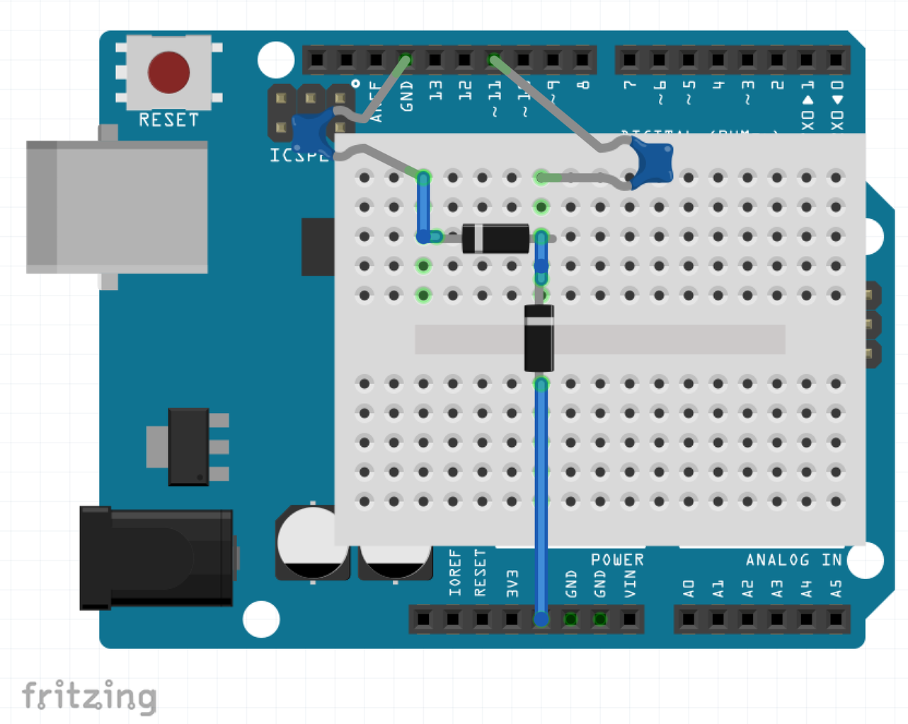
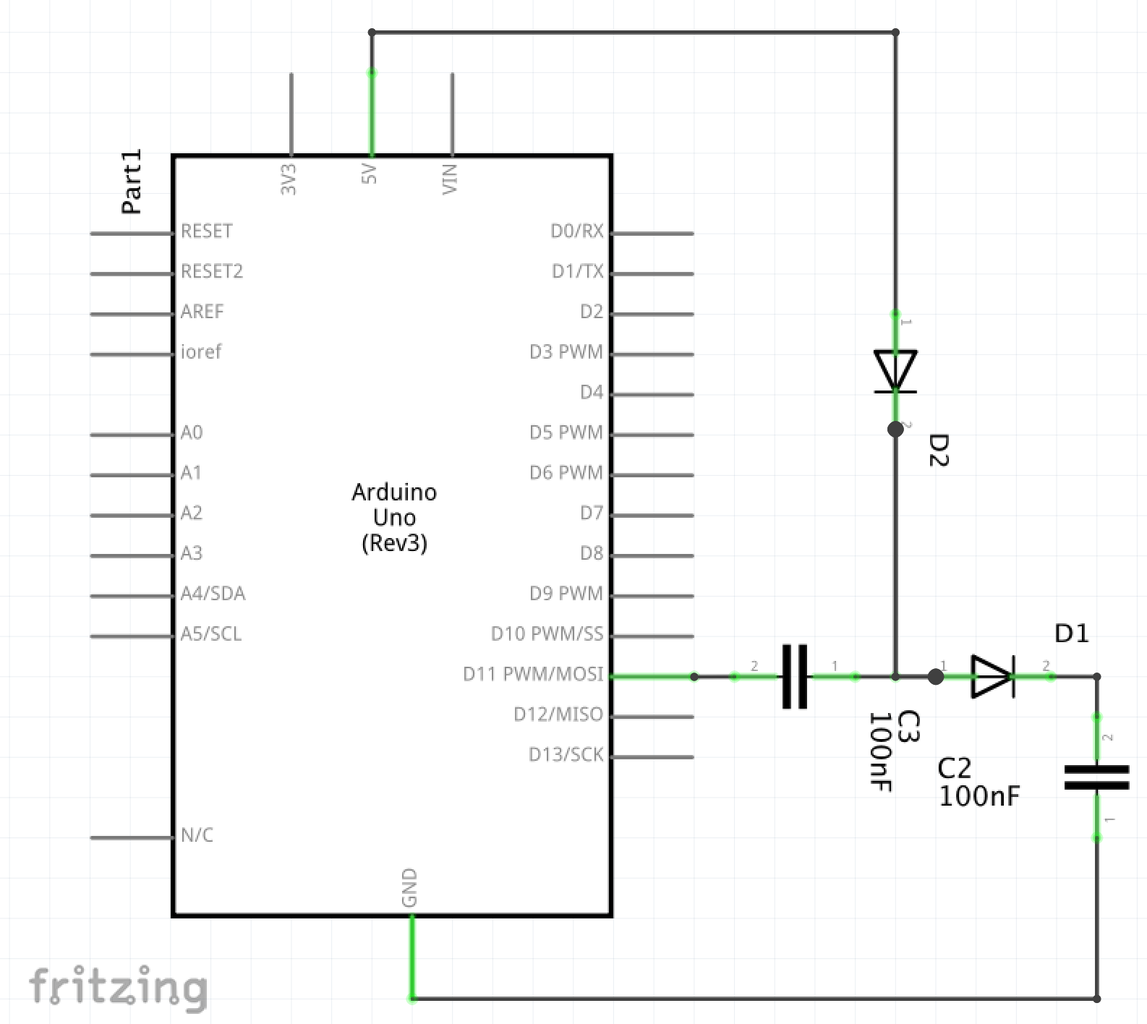

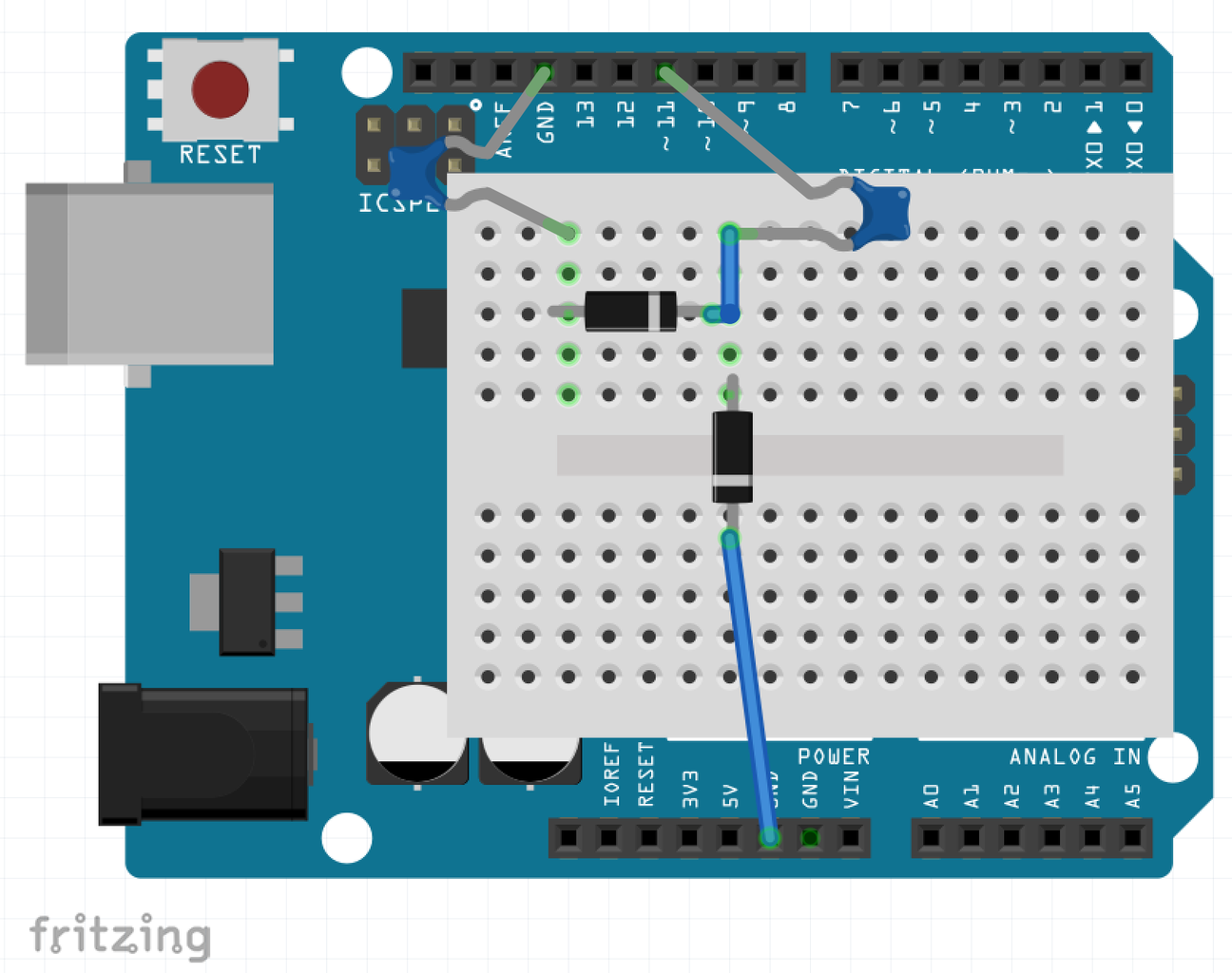
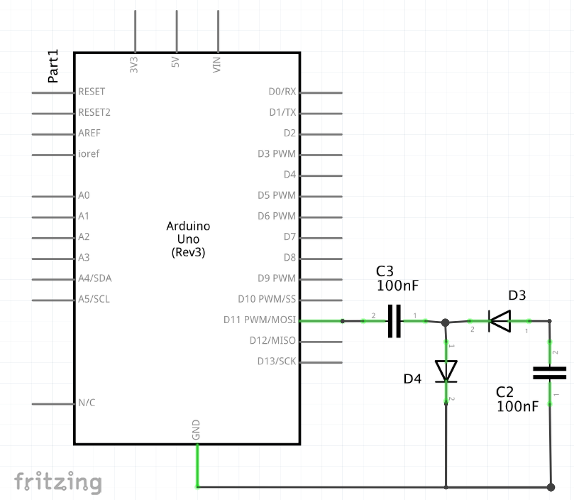

Sometimes your project requires a voltage that is higher than 5V or a negative voltage. It may be to run a MOSFET, to run a piezo element, to power an opamp, or reset an EEPROM. If the current draw is small enough, up to ~5mA, a charge pump might be the simplest solution: just 2 diodes and two capacitors connected to a pulsed signal from a timer allow to double the arduino 5V to 10V. In practice, there are 2 diode drops, so it will be more like 8.6V in practice for the doubler, or -3.6V for the inverter.
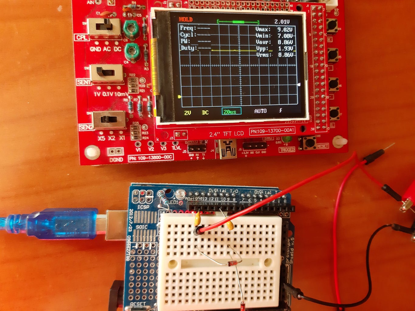
The frequency of the square wave should be sufficient to pump enough charge through the diodes. A 1muF capacitor moves 5muC of change when the voltage changes between 0 and 5V, so for a 10mA current, the frequency must be at least 2kHz. In practice, a higher frequency is better, since it reduces the ripple. With timer2 counting from 0 to 255 without prescale, the frequency is 62.5kHz, which works well.
Attachments
Step 10: Wireless Power Transfer
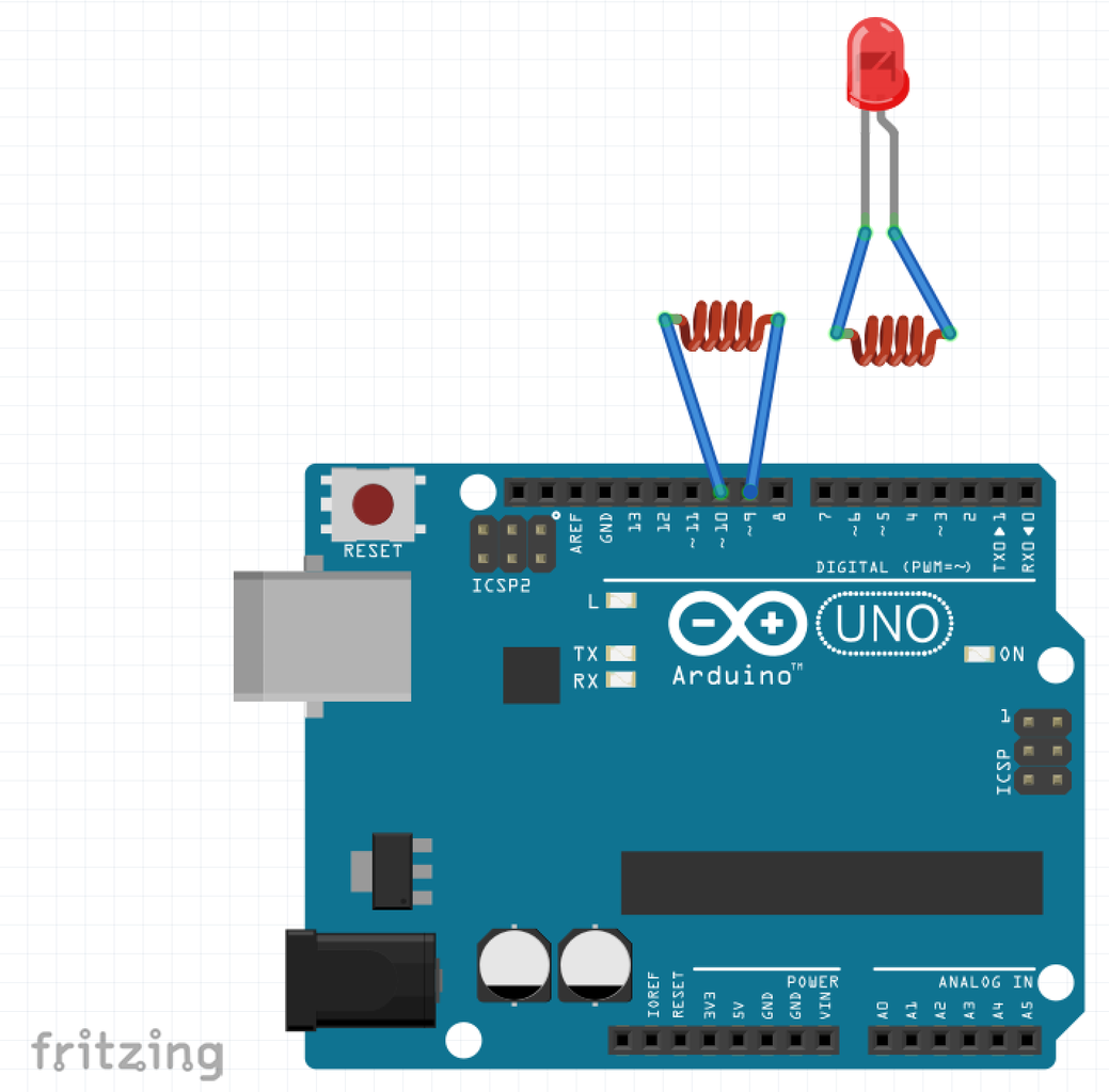
It is not uncommon to charge a smart watch without cables, but the same can easily be part of an Arduino project. A coil with a high frequency signal can transfer power to another nearby coil through induction, without electrical contact.
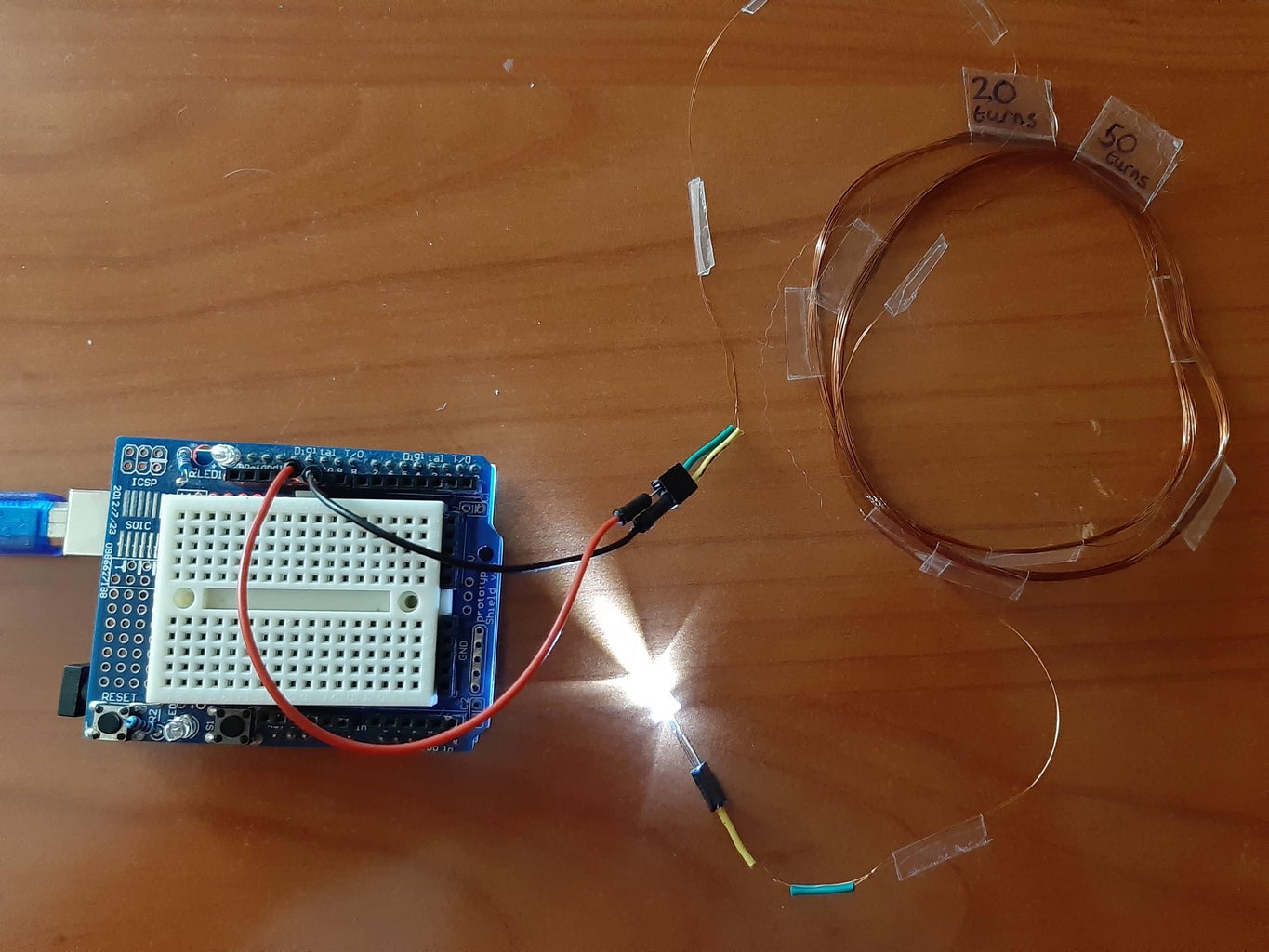
First prepare the coils. I used a paper roll of 8.5cm diameter and enameled wire of 0.13mm diameter to make 2 coils: the primary with 20 turns, the secondary with 50 turns. The self-inductance of this type of coil with N windings and a radius R is ~5muH * N^2 * R. So for N=20 and R=0.0425 gives L=85muH, which was confirmed with the component tester. We produce a signal with a frequency of 516kHz, resulting in an impedance of 2pi*f*L=275Ohm. This is high enough that the Arduino does not go into overcurrent.
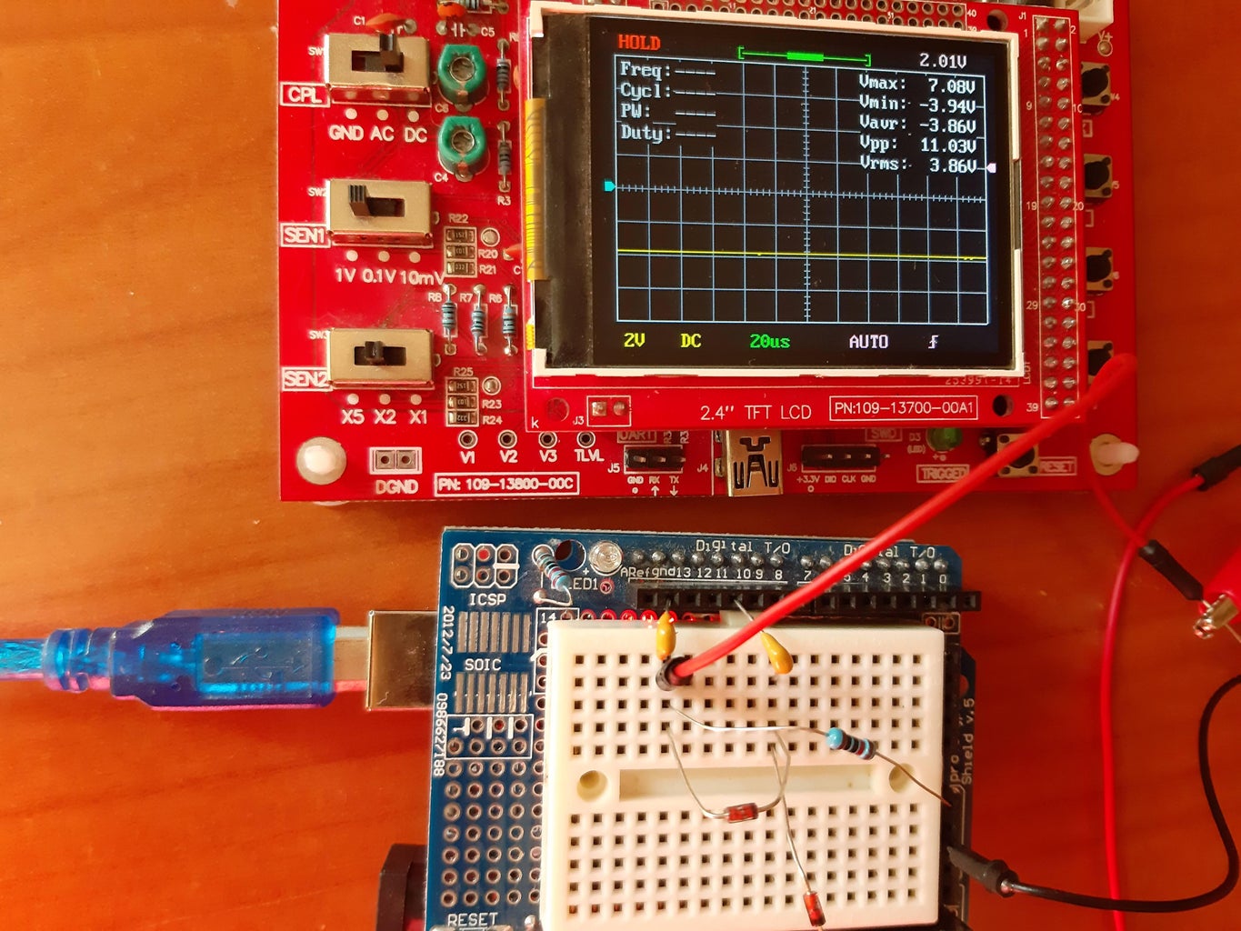
To run the coil most effectively, we’d like to use a true AC source. There is a trick that can be done: the two outputs of a timer can be run in opposite phase, by inverting one of the outputs. To make it even more similar to a sine wave, we use the Phase-correct PWM. This way, between pin 9 an 10, the voltage alternate between both 0V, pin 9 +5V, both 0V, pin 10 +5V. The effect is shown in the picture from a scope trace (with a 1024 prescale, this toy scope doesn’t have much bandwidth).
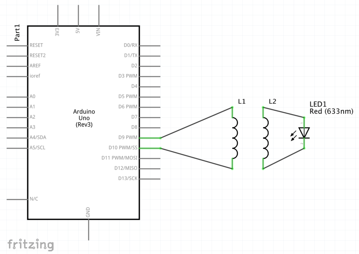
Connect the primary coil to pin 9 and 10. Connect a LED to the secondary coil. When the secondary coil is brought close to the primary, the LED lights up brightly.
Attachments

Participated in the
Arduino Contest 2020


![Tim's Mechanical Spider Leg [LU9685-20CU]](https://content.instructables.com/FFB/5R4I/LVKZ6G6R/FFB5R4ILVKZ6G6R.png?auto=webp&crop=1.2%3A1&frame=1&width=306)


