

Introduction: Arduino Weigh Scale - Step by Step Tutorial


I am an active member of a UK local Hackspace in Norwich (@NHackspace) and I regularly give potential new members their introductory tour. A common thread is that they want to learn Raspberry pi, Arduino, 3D printing and Laser cutting. I very much focus on the electronics side of things, so I have decided to give a face-to-face tutorial on working with Arduino and have decided to publish it here as well. I wanted this tutorial to be "the next step" rather than just downloading the IDE and blinking a single LED. So, I've come up this project to combine several areas of working with the Arduino so new hackers can take these concepts and take them further. The Arduino based weigh scale combines digital outputs, analogue input, using the serial monitor, programming etc.....
I am going to build the project up in 5 Steps,
Supplies

- Arduino Uno
- 1 x breadboard
- 1 x Green LED
- 4 x Blue LEDs
- 5 x 220-ohm resistors
- 1k ohm Potentiometer
- Jumer Wires
- Scale weights for calibration
- Frame for scales (could just be a cardboard box)
- Something to use as a balance arm, again could be cardboard and hot glue.
- Rubber band
- M5 x 40 Nut and Bolt
Step 1: Test the LEDs
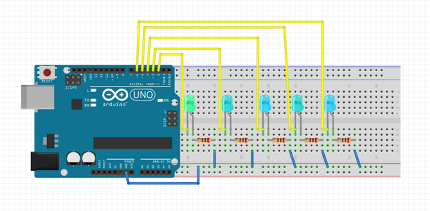
For this step all we are going to do is connect the LEDs to the Arduino Uno and test whether they are all working ok.
The Image above shows how the LEDs are connected to the Arduino Uno. We are using digital pins 2,3,4,5 and 6.
Note: We are not using Pins 0 and 1 because the Arduino Uno uses these pins for Serial Data and which can cause a conflict therefore best avoided, this is a "gotcha" which can catch out newbies.
The Long pin on an LED is called the Anode and is always connected to positive, I remember this as "A+". The Shorter pin is always connected to 0V (ground).
A resistor has to be connected in series with the LED to limit the current which stops the LED from burning out. I used 220-ohm resistors but 150-ohm and 330-ohm resistors will be ok too.
Once the LEDs are connected connect the Arduino to your computer, select the correct port and upload this code:
// Created by Tom Goff of Norwich Hackspace. Please feel free to share.
//at the start of the script we declare our global variables that we will use throughout the script
int led1 = 2;
int led2 = 3;
int led3 = 4;
int led4 = 5;
int led5 = 6;
//define digital 5 pins as pin to control the LED
// we do not use digital pins 0 and 1 as these are also used by the serial monitor


void setup()
// the setup function runs once when you press reset or power the board
{
  pinMode(led1, OUTPUT);   //Set the digital 1 port mode, OUTPUT: Output mode
  pinMode(led2, OUTPUT);   //Set the digital 2 port mode, OUTPUT: Output mode
  pinMode(led3, OUTPUT);   //Set the digital 3 port mode, OUTPUT: Output mode
  pinMode(led4, OUTPUT);   //Set the digital 4 port mode, OUTPUT: Output mode
  pinMode(led5, OUTPUT);   //Set the digital 5 port mode, OUTPUT: Output mode
  //define digital 5 pins as pin to control the LED
}


void loop()
// the loop function runs over and over again forever
{
  //we are just going to "blink" each led for 0.5 seconds to check they all work ok.
  digitalWrite (led1, HIGH); // turn led1 on
  delay (500); // delay is measued in 1/1000 of seconds so 500 is half a second
  digitalWrite (led1, LOW); // turn led1 off
  delay (500);
  digitalWrite (led2, HIGH); // turn led2 on
  delay (500); // delay 0.5s
  digitalWrite (led2, LOW); // turn led2 off
  delay (500);
  digitalWrite (led3, HIGH); // turn led3 on
  delay (500); // delay 0.5s
  digitalWrite (led3, LOW); // turn led3 off
  delay (500);
  digitalWrite (led4, HIGH); // turn led4 on
  delay (500); // delay 0.5s
  digitalWrite (led4, LOW); // turn led2 off
  delay (500);
  digitalWrite (led5, HIGH); // turn led3 on
  delay (500); // delay 0.5s
  digitalWrite (led5, LOW); // turn led3 off
  delay (500);
The code is also attached as a document.
The video explains the code and shows it working.
Attachments

Step 2: Connect the Potentiometer for Analogue Input
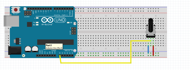

The Potentiometer is used to sense rotational movement in this project and feed this back to the Arduino. A potentiometer is basically a resistor with a connection is the middle of the resistor that moves closer to one of the end terminals as you rotate it, this increases or decreases the resistance on the middle pin.
The Arduino Uno Analogue input reads a 0-5V input and converts it to a digital value with a decimal value between 0 and 1023. Our Potentiometer varies the 5V input between 0 and 5V.
You connect one potentiometer pin to 5V from the Arduino, one pin to 0V and the middle pin to Analogue Input 0. When you turn the knob one way it increases the voltage at the middle pin to 5V, when you turn it the other way it reduces the voltage on the middle pin down to 0V. In the middle position the voltage on the middle pin will be 2.5V. The Arduino converts this Voltage to a value between 0 and 1023 (0-5V).
Connected the potentiometer as shown in the image above and try this code.
// Sketch to test the an analogue input from a potentiometer
// Created by Tom Goff of Norwich Hackspace. Please feel free to share.
//at the start of the script we declare our global variables that we will use throughout the script
int potPin = 0; // potentiometer connected to analog pin 0
float potVal;


void setup()
{
  Serial.begin(9600);
  //start the serial monitor at a baud rate of 9600
}


void loop()
// the loop function runs over and over again forever
{
  potVal = analogRead(potPin);//Read the voltage photoresistance
  Serial.println (potVal); //prints the value of the potentiometer on the serial monitor as a number between 0 and 1023
  // The "ln" at the end of print starts a new line for each value.
  delay(500);                 //delay 500ms to stop the serial monitor being overwhelmed with data
  // because it's an infinate loop the code auotmaticall loops back upto line 25
}
The video shows the code working with an explanation.
Attachments
Step 3: Using the Map() Function
In this step we are not going to change the hardware at all.
We want to change which LED is on depending on the weight applied to our scales. To do this we are going to use the map function available to us in the Arduino IDE.
If you think of our analogue value of 0-1023 like a thermometer giving lots of temperature values between 0 and 100 Celsius, you might just want the thermometer to show 5 values of water temperature such as 0, 25, 50, 75 and 100 displayed as Freezing, Chilly, Nice, Hot and Boiling. This is like mapping, more details can be found here map() - Arduino Reference
The sketch below shows how our analogue input is going to be mapped to 6 integer vales from 0 to 6.
// Sketch to test the an analogue input from a potentiometer and map it to integers
// Created by Tom Goff of Norwich Hackspace. Please feel free to share.
//at the start of the script we declare our global variables that we will use throughout the script
int potPin = 0; // potentiometer connected to analog pin 0
float potVal;
int ledVal;


void setup()
{
  Serial.begin(9600);
  //start the serial monitor at a baud rate of 9600
}


void loop()
// the loop function runs over and over again forever
{
  potVal = analogRead(potPin);//Read the voltage photoresistance
  ledVal = map(potVal, 0, 1023, 0, 5); //Photoresistor voltage value converted from 0-1023 to 0-11
  Serial.print (potVal); //prints the value of the potentiometer on the serial monitor as a number between 0 and 1023
  Serial.print (" : "); // prints a ":" between the rpotVal and ledVal
  Serial.println (ledVal); //prints the leVal and starts a new line
  delay(500);                 //delay 500ms to stop the serial monitor being overwhelmed with data
  // because it's an infinate loop the code auotmaticall loops back upto the start of the loop
}
The video shows the code working with an explanation.
Attachments
Step 4: Combining the Code

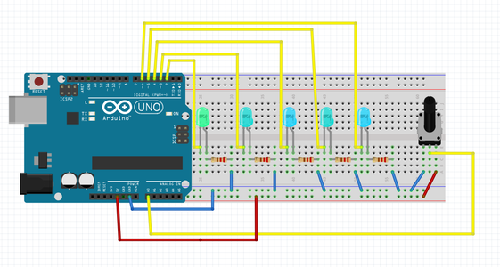
In this step we are simply going to combine the hardware from Step 1 with Step 2 as shown in the images.
One we have done this we can change our code so that we can activate a different LED depending on the analogue input value.
Now we have mapped are 0-1023 input value to 0-5 we can use this to light our LEDs using the "If" statements. Using If statements you can check whether a particular condition is true and If it is you can then do something.
For example, in our case if the ledVal is 2 then we might want to just light LED number 2.
More info on if statement can be found here - if - Arduino Reference
The video shows how the map() function is added to our code.
The code below shows how if statements are now integrated into the code to fulfil certain conditions.
// Arduino Weigh Scale - Adding If Statements
// Created by Tom Goff of Norwich Hackspace. Please feel free to share.
//at the start of the script we declare our global variables that we will use throughout the script
int led1 = 2;
int led2 = 3;
int led3 = 4;
int led4 = 5;
int led5 = 6;
int potPin = 0; // potentiometer connected to analog pin 0
float potVal;
int ledVal;


void setup()
{
  Serial.begin(9600);
  //start the serial monitor at a baud rate of 9600
  pinMode(led1, OUTPUT);   //Set the digital 1 port mode, OUTPUT: Output mode
  pinMode(led2, OUTPUT);   //Set the digital 2 port mode, OUTPUT: Output mode
  pinMode(led3, OUTPUT);   //Set the digital 3 port mode, OUTPUT: Output mode
  pinMode(led4, OUTPUT);   //Set the digital 4 port mode, OUTPUT: Output mode
  pinMode(led5, OUTPUT);   //Set the digital 5 port mode, OUTPUT: Output mode

}


void loop()
// the loop function runs over and over again forever
{
  potVal = analogRead(potPin);//Read the voltage photoresistance
  ledVal = map(potVal, 0, 1023, 0, 4); //Photoresistor voltage value converted from 0-1023 to 0-11
  Serial.print (potVal); //prints the value of the potentiometer on the serial monitor as a number between 0 and 1023
  Serial.print (" : "); // prints a ":" between the rpotVal and ledVal
  Serial.println (ledVal); //prints the leVal and starts a new line


  if (ledVal == 0) {
    digitalWrite (led1, HIGH);
    digitalWrite (led2, LOW);
    digitalWrite (led3, LOW);
    digitalWrite (led4, LOW);
    digitalWrite (led5, LOW);
  }


  if (ledVal == 1) {
    digitalWrite (led1, LOW);
    digitalWrite (led2, HIGH);
    digitalWrite (led3, LOW);
    digitalWrite (led4, LOW);
    digitalWrite (led5, LOW);
  }


  if (ledVal == 2) {
    digitalWrite (led1, LOW);
    digitalWrite (led2, LOW);
    digitalWrite (led3, HIGH);
    digitalWrite (led4, LOW);
    digitalWrite (led5, LOW);
  }
  if (ledVal == 3) {
    digitalWrite (led1, LOW);
    digitalWrite (led2, LOW);
    digitalWrite (led3, LOW);
    digitalWrite (led4, HIGH);
    digitalWrite (led5, LOW);
  }
  if (ledVal == 4) {
    digitalWrite (led1, LOW);
    digitalWrite (led2, LOW);
    digitalWrite (led3, LOW);
    digitalWrite (led4, LOW);
    digitalWrite (led5, HIGH);
  }
  delay(300);                 //delay 300ms to stop the serial monitor being overwhelmed with data
  // because it's an infinate loop the code auotmaticall loops back upto the start of the loop
}
Attachments
Step 5: Calibrating & Testing

The fifth and final stage of this project is to connect our Arduino, breadboard and circuit to our weighing scale.
I built a simple weighing scale using a laser cut frame and 3D printed balance arm. You do not need to do this as you could simply use a strong cardboard box as the supporting structure and a piece of wood, plastic or cardboard as the balance arm.
The support structure has a hole in the middle to support the potentiometer. The potentiometer has long wires soldered to it so the wires can reach the breadboard. This potentiometer will replace the one we used to build and test the circuit.
The balance arm I used is 150mm long with a hole in it to attach to the potentiometer at 50mm from one end. The short end of the balance arm is tensioned by a rubber band which is secured to the support structure with a 5mm x 40mm nut and bolt.
Once you have you scale built you need to calibrate it. To do this you change the values you wish to map taken from analogue input value. You do this firstly by reading the analogue value from the Serial Monitor when the scale is in a neutral position and then when the scale has its maximum weight (100g in my case). You then adjust the input value parameters which you have mapped accordingly, in the code below it is line 30 - "ledVal = map(potVal, 550, 700, 0, 4); //Now calibrated - 550 is the neutral value 700 is 100g" The video shows more clearly how to calibrate your scales.
// Ardino scale, final code calibrated.
//Change line 30 to calibrate.
// Created by Tom Goff of Norwich Hackspace. Please feel free to share.
//at the start of the script we declare our global variables that we will use throughout the script
int led1 = 2;
int led2 = 3;
int led3 = 4;
int led4 = 5;
int led5 = 6;
int potPin = 0; // potentiometer connected to analog pin 0
float potVal;
int ledVal;


void setup()
{
  Serial.begin(9600);
  //start the serial monitor at a baud rate of 9600
  pinMode(led1, OUTPUT);   //Set the digital 1 port mode, OUTPUT: Output mode
  pinMode(led2, OUTPUT);   //Set the digital 2 port mode, OUTPUT: Output mode
  pinMode(led3, OUTPUT);   //Set the digital 3 port mode, OUTPUT: Output mode
  pinMode(led4, OUTPUT);   //Set the digital 4 port mode, OUTPUT: Output mode
  pinMode(led5, OUTPUT);   //Set the digital 5 port mode, OUTPUT: Output mode

}


void loop()
// the loop function runs over and over again forever
{
  potVal = analogRead(potPin);//Read the voltage photoresistance
  ledVal = map(potVal, 550, 700, 0, 4); //Now calibrated - 550 is the neutral value 700 is 100g
  Serial.print (potVal); //prints the value of the potentiometer on the serial monitor as a number between 0 and 1023
  Serial.print (" : "); // prints a ":" between the rpotVal and ledVal
  Serial.println (ledVal); //prints the leVal and starts a new line


  if (ledVal == 0) {
    digitalWrite (led1, HIGH);
    digitalWrite (led2, LOW);
    digitalWrite (led3, LOW);
    digitalWrite (led4, LOW);
    digitalWrite (led5, LOW);
  }


  if (ledVal == 1) {
    digitalWrite (led1, LOW);
    digitalWrite (led2, HIGH);
    digitalWrite (led3, LOW);
    digitalWrite (led4, LOW);
    digitalWrite (led5, LOW);
  }


  if (ledVal == 2) {
    digitalWrite (led1, LOW);
    digitalWrite (led2, LOW);
    digitalWrite (led3, HIGH);
    digitalWrite (led4, LOW);
    digitalWrite (led5, LOW);
  }
  if (ledVal == 3) {
    digitalWrite (led1, LOW);
    digitalWrite (led2, LOW);
    digitalWrite (led3, LOW);
    digitalWrite (led4, HIGH);
    digitalWrite (led5, LOW);
  }
  if (ledVal == 4) {
    digitalWrite (led1, LOW);
    digitalWrite (led2, LOW);
    digitalWrite (led3, LOW);
    digitalWrite (led4, LOW);
    digitalWrite (led5, HIGH);
  }
  delay(300);                 //delay 300ms to stop the serial monitor being overwhelmed with data
  // because it's an infinate loop the code auotmaticall loops back upto the start of the loop
}

![Tim's Mechanical Spider Leg [LU9685-20CU]](https://content.instructables.com/FFB/5R4I/LVKZ6G6R/FFB5R4ILVKZ6G6R.png?auto=webp&crop=1.2%3A1&frame=1&width=306)


