

Introduction: Fun Festive Custom PCB


This project is a simple introduction to designing, building and coding a simple custom PCB with a festive feel. The PCB can be used as earrings, a badge, a tree decoration or a desk ornament.
The PCB was designed to be built at a Norwich Hackspace Festive gathering - Norwich Hackspace - home - to give members with a desire to learn about electronics, soldering and Arduino some practical experience with guidance from more experienced members.
The Arduino UNO has an ATmega328 microcontroller at it's heart with a variety of components added to the PCB to make it very user friendly. This festive PCB in essence is a very stripped down Arduino UNO with many of the components removed such as the Crystal Oscillator, Power Jack, USB programming connectors, voltage regulators etc.... But don't worry it can still be programmed as an Arduino as I will explain later.
The PCB can be used as a desk or table decoration with the 2 x AAA battery pack or as a piece of festive jewellery with the smaller lighter 2 x CR2032 battery pack.
Supplies


The materials used to build this festive piece of electronic craft includes:
- PCB x 1
- ATmega328P DIL Microcontroller x 1 (same as Arduino UNO)
- 5mm LEDs x 7
- 470 ohm resistors x 7
- 10k ohm resistor x 1
- AAA x 2 Battery Holder x 1 (option for desk or table decoration)
- CR2032 x 2 Battery Holder x 1 (option for desk or table decoration)
- Solder
- PLA Filament (not essential)
The tools I used for this build are:
- Laptop
- Soldering Iron
- Wire cutters
- Blue Tack
- 3D Printer (not essential)
The software I utilised in this build includes:
- TinkerCAD
- Fusion 360
- Fritzing
- Inkscape
Step 1: Designing a Custom Shape PCB

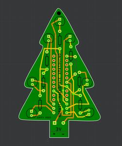
To design the PCB I used two software packages, Inkscape and Fritzing. Inkscape was used to design the custom shape of the PCB and Fritzing was used add the components and connecting wire traces.
I have embedded a YouTube video explaining in detail how to go from creating a custom shape in Inkscape to a final PCB design in Fritzing.
Please leave me a comment if you want a copy of the .zip file of the completed PCB so you can order from a company such as JLC PCB or PCBway.
Step 2: Adding the Barebones ATmega328 to the Arduino IDE

Because we are using the absolute bare minimum of components to run the Atmega328 microcontroller it is not included in the Arduino IDE as standard. If you are using the Arduino IDE to upload your code then you will need to add this board to your IDE called ATmega328 on a breadboard (8MHz Internal Clock). This is because to run the ATmega328 microprocessor without an external clock signal the microprocessor needs a different "bootloader" to that of the Arduino UNO. Basically it sets up the internal fuses inside the microcontroller in a different way and tells it to use the it's internal 8MHz clock as opposed to the external clock signal.
The hardest part of this project for most people is adding the ATmega328 on a breadboard (8MHz Internal Clock) to your Arduino IDE.
There is a fantastic Arduino tutorial on how to add the ATmega328 on a breadboard (8MHz Internal Clock) to your Arduino IDE on this link - From Arduino to a Microcontroller on a Breadboard | Arduino Documentation.
The instructions for adding the ATmega328 on a breadboard (8MHz Internal Clock) are as follows:
- Download (from the link above) the hardware configuration for the IDE version you are using: breadboard-1-6-x.zip, Breadboard1-5-x.zip or Breadboard1-0-x.zip. The configuration you use will depend on which IDE you use, I use 1.8.13 and found breadboard-1-6-x.zip worked for me.
- Create a "hardware" sub-folder in your Arduino sketchbook folder (whose location you can find in the Arduino preferences dialog). If you've previously installed support for additional hardware configuration, you may already have a "hardware" folder in your sketchbook.
- NOTE: I found I actually had a hardware folder in C:\Program Files (x86)\Arduino which was different to the Arduino tutorial and I added and unzipped breadboard-1-6-x.zip to this location.
- If you created a "hardware" folder in your sketch book move the breadboard folder from the zip archive to the "hardware" folder of your Arduino sketchbook.
- Restart the Arduino software.
Once you have completed the above steps you should see "ATmega328 on a breadboard (8 MHz internal clock)" in the Tools > Board menu. You will need to select this option to upload your code.
Step 3: Adding the Components & Soldering


When I solder the components to a PCB I usually start with the lowest components (such as the resistors) and then work up to the highest components (the LEDs) as it makes it easier. The order I soldered the components was:
- 7 x 470 ohm LED resistors on the front.
- 7 LEDs on the from.
- 1 x 10k ohm resistor on the back.
- The Microcontroller socket on the back.
- The battery pack power leads.
On the front of the PCB all the resistors are 470 ohm and need to be positioned in there holes. Once I've pulled the leads through I bend them outwards at 45 degrees to stop the resistor falling out of the PCB. I then solder all the leads in place and trim off the excess lead.
To solder the connection remember to heat the connection of the PCB and the lead and then feed in just enough solder to make a neat joint. Then pull the soldering iron away and let the joint cool making sure not to move it.
The resistors were designed into the PCB to look like little candy canes :) The resistors are there to limit the current going to the LEDs and prevent it from becoming damaged and failing. They also mean your battery can last longer. When you place the resistors on the PCB in doesn't matter which way round they go. The 10k ohm resistor on the back is to prevent the microcontroller resetting by holding pin 1 high.
The LEDs are a diode which means current can only go through them in one direction so it's very important they are put in the correct way round. An LED has two wires from it, usually called legs, and one is longer than the other. the Long leg goes to the positive and the short leg goes to the negative. If you look carefully you will see that the LEDs are mounted in the semi-circles on the PCB. The flat part of the semi-circle marks the position of the short LED leg.
After I soldered in all the LEDs I then flipped the PCB over and soldered in the 10k ohm resistor.
A really useful tip for soldering components to a PCB is to place them in the correct position and then hold them there temporarily with blue tack. This enables you to turn the PCB upside-down without all the components falling out. This is how I soldered the microcontroller socket.
When you finally solder the battery pack power leads ensure the red wire goes to the positive terminal and the black wire goes to the negative terminal.
Step 4: Writing a Sketch

Writing a sketch for the ATmega328p mounted on this PCB is much the same as writing a sketch for an Arduino UNO or Nano. The only difference is it's only worth writing Pins 5 -11 high as these are the only pins connected to LEDs. I have attached a photo showing how LEDs are connected to the pins.
This is a great platform for experimenting with different lighting patterns using different sketches however I have included two sketches that you can use as a starting point.
The first sketch simply sets all the pins to outputs in the void setup () function and then in the void loop () function it turns all the outputs to high (on) waits 300 milliseconds and then sets all the outputs to low (off) waits 300 milliseconds and then goes back up to the start of the loop and continues to repeat so long as the power is on.
void setup() {
  // put your setup code here, to run once:
  // set all the pins to outputs;
  pinMode (5, OUTPUT);
  pinMode (6, OUTPUT);
  pinMode (7, OUTPUT);
  pinMode (8, OUTPUT);
  pinMode (9, OUTPUT);
  pinMode (10, OUTPUT);
  pinMode (11, OUTPUT);
}

void loop() {
  // put your main code here, to run repeatedly:
  // turn all the pins on
  digitalWrite (5, HIGH);
  digitalWrite (6, HIGH);
  digitalWrite (7, HIGH);
  digitalWrite (8, HIGH);
  digitalWrite (9, HIGH);
  digitalWrite (10, HIGH);
  digitalWrite (11, HIGH);
  // wait 300 ms
  delay (300);
  // turn all the pins off
  digitalWrite (5, LOW);
  digitalWrite (6, LOW);
  digitalWrite (7, LOW);
  digitalWrite (8, LOW);
  digitalWrite (9, LOW);
  digitalWrite (10, LOW);
  digitalWrite (11, LOW);
  // wait 300ms
  delay(300);
  // go back to the begin
The second sketch is more interesting as it puts the left and right hand columns of LEDs into an array. in the setup () function a for loop is used to set all the pins to outputs as this is a quicker way to perform a repetitive function. In the loop () function a for loop is used to turn on each of the LEDs either side, starting at the bottom, on sequentially by looping through the two arrays. Once all the side LEDs are on it then flashes the top LED on and off a few times and then goes through a for loop to turn off each of the LEDs either side on sequentially, starting at the top, by looping through the two arrays. It then goes back to the top of the loop () function and starts again continuously.
int timer = 100;           // The higher the number, the slower the timing.
int ledArray1[] = {8, 7, 6};   // an array of pin numbers to which LEDs are attached
int ledArray2[] = {9, 10, 11};     // an array of pin numbers to which LEDs are attached

void setup() {
  // for loop to make all pins outputs
  for (int i = 2; i < 12; i++) {
    pinMode(i, OUTPUT);
  }
}

void loop() {
  // loop from the lowest pin to the highest:
  for (int i = 0; i < 3; i++) {
    // turn the pin on:
    digitalWrite(ledArray1[i], HIGH);
    digitalWrite(ledArray2[i], HIGH);
    delay(timer);
    // turn the pin on:
  }
  // flash top Led 3 times
  for (int j = 0; j < 3; j++) {
    // turn the pin on:
    digitalWrite(5, HIGH);
    delay(timer);
    //turn the pin off:
    digitalWrite(5, LOW);
    delay(timer);
  }
  digitalWrite (5, HIGH);
  delay (1000);
  digitalWrite (5, LOW);
  // loop from the highest pin to the lowest:
  for (int x = 3 - 1; x >= 0; x--) {
    delay(timer);
    // turn the pin off:
    digitalWrite(ledArray2[x], LOW);
    digitalWrite(ledArray1[x], LOW);
    delay(timer);
  }
  delay(1000);
}
Attachments

Step 5: Testing Sketch With Tinkercad

The pattern the LEDs blink are reprogrammable meaning you can have any pattern you can think of. Tinkercad is a brilliant resource for testing you lighting patterns by running your simulations without having to touch the hardware. What I like about Tinkercad is that you can experiment with different hardware and software configurations quickly and easily and anywhere you like.
Please have a look at the video showing you how I used Tinkercad to try out a sketch.
Step 6: Uploading the Code


The code can be uploaded to the PCB a variety of ways I am going to cover include:
Using and Arduino UNO - This is the simplest way to upload your code. All you need to do is carefully remove the existing ATmega328 microprocessor from your Arduino development board and insert the microprocessor you want to program. Make sure you select tools / board / boards manage / breadboard-avr / ATmega328 on a breadboard (8MHz Internal Clock). Then click upload and your sketch should upload to your microcontroller.
Using an AVRISP Programmer - I pre-loaded 20 ATmega328 microcontrollers with a sketch ready to use so I used an AVRISP Programmer. The AVRISP Programmer connects to 6 pins on the microcontroller which are Vcc, GND, Reset (1), MOSI (11), MISO (12) and SCK (13) and loads the program with a serial connection to the microcontroller. I made up a simple circuit on prototyping board with a ZIF (Zero Insertion Force) IC Socket to enable me to program the microcontrollers quickly. The ZIF socket also enables me to insert the microcontrollers easily without risk of damaging them. The programming board also has LEDs connected so that I can test the microcontroller with the sketch uploaded. The uploading procedure is as follows; Select tools / programmer / USBtinyISP to select the programmer you are using. Then click sketch / upload using programmer and your code should transfer to the microcontroller.
I have shown a schematic of the programming interface I built for quick program uploading.
If you are using fresh new IC's you will need to burn a bootloader onto the Microcontroller, there's a great Instructable on how to do this here How to Burn the Arduino BootLoader on to a AtMega328p Chip : 4 Steps - Instructables.
Step 7: Finishing Off

To finish off I designed a simple "bucket" in Fusion 360 which I then 3D printed. This was glued to the battery holder with epoxy glue and then the PCB was placed in the slot making it a free standing desk or table decoration.

Participated in the
Jewelry Contest

![Tim's Mechanical Spider Leg [LU9685-20CU]](https://content.instructables.com/FFB/5R4I/LVKZ6G6R/FFB5R4ILVKZ6G6R.png?auto=webp&crop=1.2%3A1&frame=1&width=306)


