

Introduction: Bucky Touch: Light-up Dodecahedron Instrument


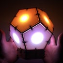


About two years ago, I built a big 120 face LED geodesic dome that plays music with a MIDI output. However, it was a difficult build and the sensors weren't completely reliable. I decided to build the Bucky Touch, a smaller version of my geodesic dome that is easier to construct and has upgraded capacitive touch sensors. The Bucky Touch is designed with both a MIDI and audio output, so you can either use a MIDI device (e.g. a computer or MIDI keyboard) to play the Bucky Touch OR you can directly hook up the Bucky Touch to an amplifier and speaker.
My first prototype in this project was similar, but does not have touch-sensitive faces and instead provides break-out pins that provide access to digitial I/O pins, a TX (transmit) pin, a RX (receive) pin, reset pin, and ground pin. This version I called the Bucky Glow. The pins enable you to connect the Bucky Glow to sensors (e.g. capacitive touch, infrared, ultrasonic), motors, MIDI jacks, and any other electronics you can think of.
This instructable goes through assembly of the Bucky Touch, which is more like a musical instrument in comparison to the Bucky Glow.
Step 1: Supply List


Materials:
1. Two sheets of 16" x 12" 0.118" thick MDF
2. One sheet of 12" x 12" 0.118" thick translucent white plexiglass
3. WS2801 or WS2811 pixel LED strip (11 LEDs): https://www.amazon.com/gp/product/B01AG923GI/ref=o...
4. Arduino Nano: https://store.arduino.cc/usa/arduino-nano
5. Prototype board
6. ITO (Indium Tin Oxide) Coated PET Plastic - 100mm x 200mm https://www.adafruit.com/product/1309
7. 11X 2MOhm resistors
8. 11X 1kOhm resistors
9. 10k resistor for audio output
10. 2X 0.1uF capacitors for audio output
11. MIDI jack:
12. Toggle switch: https://www.digikey.com/product-detail/en/e-switc...
13. Push button: https://www.amazon.com/DAOKI-Miniature-Momentary-...
14. Stereo audio jack: https://www.amazon.com/gp/product/B01MRX7KA1/ref=...
15. Header pins
16. 2X M3 nuts
17. 2X M3x12 bolts
18. Wire wrap wire
19. Scotch tape
20. Solder
21. Electrical tape
22. MIDI to USB cable if you want to play MIDI with computer
Tools:
1. Laser cutter
2. 3D printer
3. Wire cutters
4. Soldering iron
5. Scissors
6. Allen wrench
7. Hot glue gun
8. Wire wrap tool
Step 2: System Overview


At the heart of the Bucky Touch is an Arduino Nano. The data pin and clock pin of a WS2081 addressable LED strip is connected to pin A0 and A1, respectively. Each face of the dodecahedron has a capacitive touch sensor connected with a 2.2Mohm resistor to the send signal coming from pin A2. The receive pins are A3, D2-D8, and D10-D12. Here is a link to capacitive touch sensors: http://playground.arduino.cc/Main/CapacitiveSensor
The Bucky Touch has both a MIDI output and mono audio signal. Both these signals are discussed in Step 6. The TX pin is used for the MIDI and a PWM signal from pin 9 is used for the audio. To switch between MIDI and mono output, there is a toggle switch connected to pin A3.
The Arduino is programmed to read all the capacitive touch sensors to determine which pentagon key is being pressed by the user. It then outputs signals to update the LEDs and produce a sound, either MIDI or mono audio depending on the direction the toggle switch is flipped.
Step 3: Designing and Cutting the Chassis


The chassis of the Bucky Touch was designed in Fusion 360. My goal was to design the chassis so it could be assembled without using any glue. The LEDs slide into pentagonal faces, and walls are used to separate the light and provide support for plexiglass above the LEDs. The assembled dodecahedron then attaches to a base that holds the Arduino, jacks, and other electronics. There is a total of 113 MDF parts, and 11 plexiglass parts.
After designing the fully assembled structure, I exported the surface of each part as a DXF file by first starting a sketch on the surface. Then I exited the sketch mode, right-clicked on the new sketch, and then selected "Save as DXF." See the gif above.
The laser cutter I have accepts PDF files, so I needed a program to import DXF files and arrange the vectors of each part for cutting. I started by using Inkscape, a free vector graphics software. Inkscape works pretty well, but I wanted to find a program more similar to Adobe Illustrator. After some research, I discovered Graphic by Autodesk. Graphic costs a one-time fee of $30 and has similar interface and features to Illustrator, so I think it is a great deal for those searching for cheaper graphic design software without the annual fee. One downside is Graphic can't import DXF files. So I ended up importing DXF files to Inkscape, and then exporting them as EPS so they could be uploaded to Graphic. It is not the most efficient method, but it tells you how user-friendly I found Graphic to be.The parts were arranged over a 16"x12" sheet and exported as a pdf for my Epilog Zing laser cutter.
Before cutting all the parts, I tested the fit between joints by cutting a few parts. I wanted the joints to be tight enough so they held together without glue, so it took a lot of cutting and resizing until I was satisfied with the fit. Above are some partly assembled prototypes. I also have all the parts laid out for an older prototype with slightly different parts.


Step 4: Mounting the LEDs


Push the LED pixels through the MDF pentagonal faces (part B). They should fit snuggly, but to be safe it is best to hot glue them into place like Baweja Akshay does for his DOT2 LED table. Add some extra cables to extend the length of the 5V, GND, data, and clock signals of the LED strip. There should be a total of 11 LEDs in the Bucky Touch. The last pentagonal face is for the bottom of the instrument.
Cut eleven 30-40cm strips of wire cut wire and label them with tape corresponding to the LEDs (1 to 11). These wires are for the capacitive touch sensors, which are completed in Step 9. Pull the wire through the pentagonal faces and tape them down so they stay in place.
Step 5: Wall and Face Assembly


Put the pentagonal faces (Part B) together in the order shown in the schematic using the V-joints (Part D). The order is crucial so that the LEDs can be updated in the correct order on the dodecahedron. Make sure the joints are pushed all the way together. Squeeze the ball inward as a final measure. Pull the wires for the LEDs and capacitive touch sensors through the bottom of the dodecahedron. NOTE: In some of the images above, I am showing assembly with an older prototype. The only difference with this older model is that it does not have the wires for the capacitive touch sensors.
Next slide the trapezoidal walls (Part C) into the V-joints. These walls separate the light from different LEDs and support the plexiglass above the LEDs. If everything is completely pushed in, then the plexiglass should rest flush at the top of the walls.
Step 6: MIDI and Audio Output


The Bucky Glow has both MIDI and mono audio output. For a review of MIDI and Arduino, check out this link. I like MIDI because it is easy to set up with Arduino and provides audio from countless clean-sounding instruments with a click of a button. The downside is that it requires a MIDI playing device to decode the signals and convert them into an audio signal. Also, developing your own analog signals gives you more control and a better understanding of the signal that is actually produced and played into speakers.
Creating analog audio signals is challenging work that requires knowledge of oscillating circuits and more complex circuit design. I started designing oscillators for this project and made some progress, when I found a terrific article by Jon Thompson on creating complex audio signals using a single PWM pin on the Arduino. I think this was a perfect middle ground between MIDI signals and more complicated analog circuit design. The signals are still produced digitally, but I saved a lot of time in comparison to building my own oscillating circuits. I still want to try this some time, so any suggestions for good resources would be much appreciated.
Jon explains how you can generate a 2MHz 8-bit digital output with a single pin, which can be converted to an analog audio signal after smoothing through a low-pass filter. His article also explains some basics of Fourier analysis, which is required for understanding more complex waveforms. Instead of a pure tone, you can use this approach for generating more interesting audio signals. It is working well enough for me so far, but I think there is even more potential with this technique! See the video above for a preliminary test of switching between audio and MIDI output.
Test the MIDI and audio output on a breadboard before moving on to soldering components on the prototype board.
Attachments
Step 7: Soldering the Board and Mounting Arduino

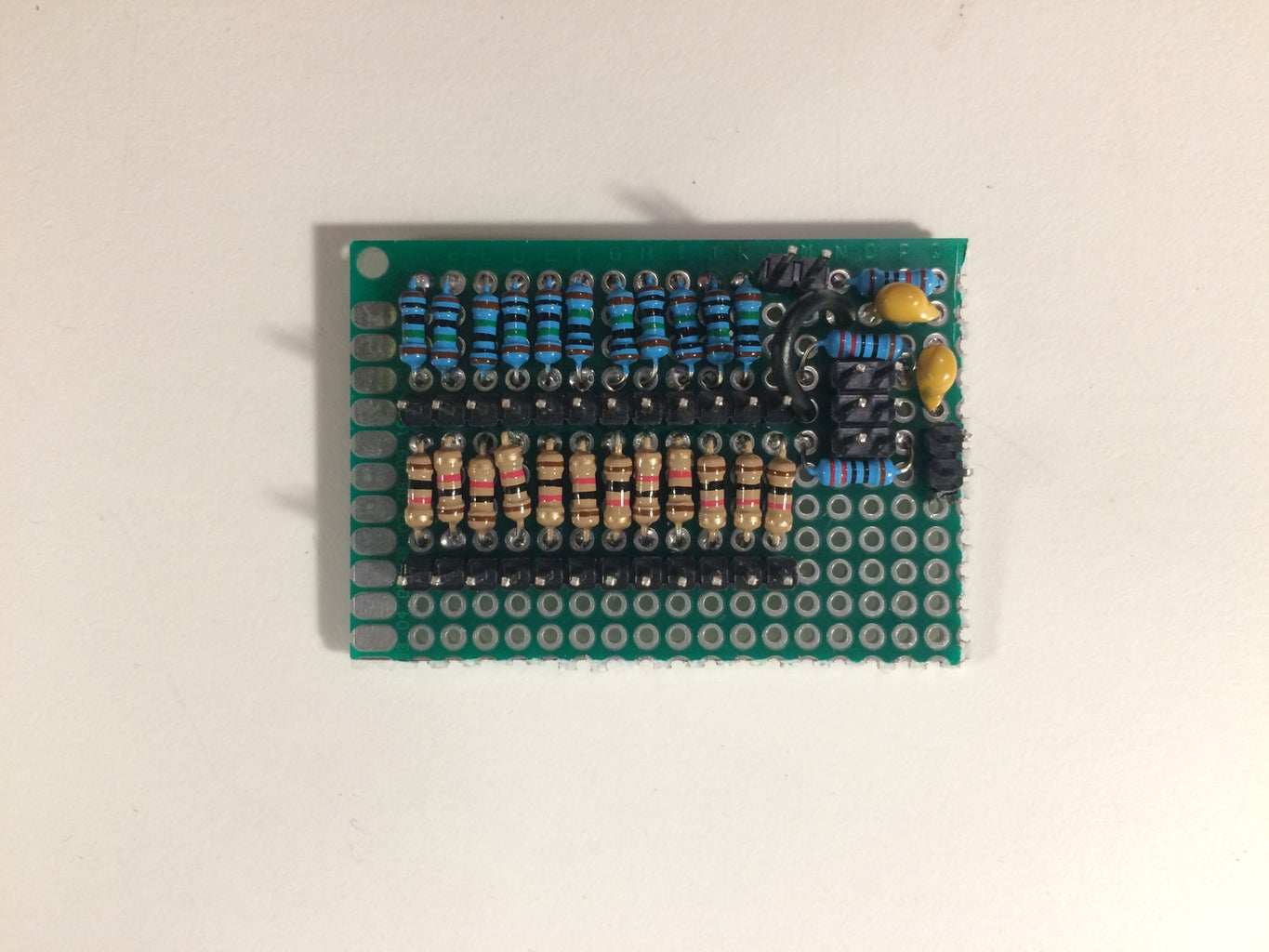


Collect the resistors, capacitors, header pins, and prototype board. Break down the prototype board to 50mm x 34mm. Add the 10MOhm resistors in the top left cover, followed by the header pins. These header pins will connect to the capacitive touch sensors. Continue adding the components by following the schematic of the Bucky Touch. You should have pins for the capacitive touch send signal, the eleven capacitive touch receive signals, the MIDI signal, the audio signal (out of arduino and into the mono stereo jack), 5V, and GND.
I designed a custom mount for holding the Arduino and prototype board in the bottom base of the Bucky Touch. 3D print this part using the STL file provided. Now slide the Arduino Nano and prototype board into the mount. Note that the Arduino Nano will need to have its pins facing upward. Slide two M3 nuts into the mount. These will be used to connect the mount to the base of the Bucky Touch.
Use wire-wrap wire to make connections between the Arduino and the prototype board as shown in the schematic. Also connect the capacitive touch wires to the header pins on the prototype board.
Attachments

Step 8: Assembling the Base


Push the Midi jack, audio jack, and toggle switch through the base face with the appropriate holes. You can either screw in the jacks or glue them in the back. For the reset switch, you will need to carve out a small square so it rests flush with the front of the face. Solder wire-wrap wire onto the switches so they can be connected to the prototype board and Arduino.
Now it is time to connect the base walls to the base bottom. Slide one wall at a time into the base bottom and base connector joints (Part G). You have to slide the wall into the side with larger notches, and then press the wall down. The wall should snap into place. After connecting the walls with the holes for the Arduino, slide the Arduino/prototype board assembly into place and connect it using the M3x12 bolts. You may have to wiggle the M3 nuts until they are in the correct position.
After connecting all the base sides, solder the jack wires to the appropriate pins. At this point, it is a good idea to test the audio and MIDI signals using the code I have provided here. If it's not working, check your connections before moving onto the next step.
Step 9: Making the Plexiglass Conductive


I tried several ways to make the plexiglass a key for the instrument. In my geodesic dome project, I used IR sensors for detecting when the user's hand was close to the surface. However, they were not not reliable because of IR radiation of the environment, crosstalk between IR sensors, and inaccurate measurements. For the Bucky Touch I thought about three potential solutions: frequency encoded IR sensors, pushbuttons, and capacitive touch. The pushbuttons and frequency encoded IR sensors didn’t work because of problems I talk about on my Hackaday page.
The challenge for capacitive touch sensor is that most conductive material is opaque, which wouldn’t work for the Bucky Touch because light has to make it through the plexiglass. Then I discovered the solution: ITO coated plastic! You can buy a 200mm x 100mm sheet from Adafruit for 10bucks.
First I cut the ITO coated plastic into strips and taped them onto the plexiglass in an “X.” Make sure the conductive sides of the plastic are facing each other. Check by measuring the resistance using a multimeter. Initially I bent the plastic and connected copper to solder wires for the capacitive touch. BIG MISTAKE: do not bend the ITO coated plastic! Bending the plastic breaks the connection. Instead I taped about an inch of wire-wrap wire to the plastic and that worked great. Remember that wire-wrap wire from Step 4 that was fed through the pentagonal LED face? It is now time to use them for the capacitive touch sensors. Expose the wire and tape it to the conductive plastic taped to the plexiglass. Repeat this for all 11 plexiglass faces.
Now is a good time to run some tests to make sure your plexiglass faces are functioning as capacitive touch sensors.
Step 10: Mounting the Plexiglass


Add the joints (Part E and F) to the bottom of the Bucky Touch that connect the bottom with all the electronics to the top with the LEDs. Then partly push the pup-joints (Part H) into the Bucky Touch walls so there is enough space to slide in the plexiglass. The plexiglass can only fit if you don’t push the pup-joints in all the way, so be careful. Once you have placed all 11 plexiglass faces, push the pup joints in completely to lock in the plexiglass faces. It should be a snug fit.
Wrap and solder the other end of the capacitive touch wires to the appropriate pins on the prototype board, and test your capacitive touch sensors again. Finally, connect the top and bottom parts together using the joints (Part E and F). Make sure not to pull on any wires. Congratulations, the Bucky Touch is fully assembled!
Step 11: Older Prototypes


Before the Bucky Touch, I built a few other prototypes without touch sensors. The first prototype worked well, but had an unstable base that flared outward. Therefore, I made the base of the second version more sturdy and added breakout pins to make the device customizable. I called this device the Bucky Glow. The breakout pins enable you to connect the Bucky Glow to sensors (e.g. capacitive touch, infrared, ultrasonic), motors, MIDI jacks, and any other electronics you can think of. I also created an app in Processing for developing unique light patterns. The app can be downloaded here. Watch the video above for details about the Bucky Glow. For the Bucky Touch, I wanted to have the faces touch-sensitive so it was more like a musical instrument.
Step 12: Coding the Bucky Touch


With the Bucky Touch fully assembled, it is time for the software. The first thing is to test the levels of the capacitive touch sensors. Upload the CAPtestWithLEDfeedback program onto the Bucky Touch and display the serial plotter to check the response. Flip through the different plexiglass panels and record the cutoff level for each sensor.
The program buckyTouch1v2 will get the BuckyTouch playing music. It is the complete program that toggles between MIDI and audio output. For these programs you will need the following libraries:
CapacitiveSensor.h
Adafruit_WS2801.h
MIDI.h
avr/interrupt.h
Next steps will be programming the Bucky Touch to go beyond just a musical instrument and to work on the audio output of the device. Thanks for reading the instructable!

Second Prize in the
Audio Contest 2018


![Tim's Mechanical Spider Leg [LU9685-20CU]](https://content.instructables.com/FFB/5R4I/LVKZ6G6R/FFB5R4ILVKZ6G6R.png?auto=webp&crop=1.2%3A1&frame=1&width=306)


