

Introduction: Desktop Gigapixel Microscope


In optical microscopes, there is a fundamental trade-off between field-of-view and resolution: the finer the detail, the smaller the region imaged by the microscope. One way to overcome this limitation is to translate the sample and acquire images over a larger field-of-view. The basic idea is to stitch together many high resolution images to form a large FOV. In these images, you get to see both the full sample, as well as fine detail in any portion of the sample. The result is an image consisting of about a billion pixels, much larger in comparison to the pictures taken by a dSLR or smart phone, which typically have around 10 to 50 million pixels. Check out these gigapixel landscapes for an impressive demonstration of the massive amount of information in these images.
In this instructable, I will go over how to build a microscope capable of imaging a 90mm x 60mm field-of-view with pixels corresponding to 2μm at the sample (although, I think the resolution is probably closer to 15μm). The system uses camera lenses, but the same concept can be applied using microscope objectives to get even finer resolution.
I uploaded the gigapixel images I acquired with the microscope on EasyZoom:
1970 National Geographic magazine image
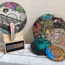
Crochet tablecloth my wife made
Other resources:
Optical microscopy tutorials: https://www.microscopyu.com/
Optical resolution: https://en.wikipedia.org/wiki/Diffraction-limited_...
In addition to image stitching, recent progress in computational imaging makes gigapixel microscopy possible without even moving the sample!
Step 1: Supply List


Materials:
1. Nikon dSLR (I used my Nikon D5000)
2. 28mm focal length lens with 52mm threading
3. 80mm focal length lens with 58mm threading
4. 52mm to 58mm reverse coupler
5. Tripod
6. Seven sheets of 3mm thick plywood
7. Arduino Nano
8. Two H-bridge L9110 https://www.amazon.com/gp/product/B00NN6EB3U/ref=o...
9. Two IR emitters
10. Two IR receivers
11. Push button
12. Two 2.2kOhm resistors
13. Two 150Ohm resistors
14. One 1kOhm resistor
15. Remote release for Nikon camera https://www.amazon.com/gp/product/B00MCA191K/ref=o...
16. Black poster board
17. Hardware kit: https://www.amazon.com/gp/product/B06XQMBDMX/ref=o...
18. Two stepper motors (I used Nema 17 Bipolar step motor 3.5V 1A)
19. Two 2mm lead screws
20. Four pillow blocks
21. Two lead screw nuts
22. Two bearing slide bushing and 200mm linear shafts: https://www.amazon.com/gp/product/B01KL7I65W/ref=p...
23. 5V power supply: https://www.amazon.com/gp/product/B01M0KLECZ/ref=o...
24. Wire wrap wire
Tools:
1. Laser cutter
2. 3D printer
3. Allen wrenches
4. Wire cutters
5. Wire wrap tool
Step 2: System Overview

To translate the sample, two stepper motors aligned in orthogonal directions move a stage in the x and y direction. The motors are controlled using two H-bridges and an Arduino. An IR sensor positioned at the base of the stepper motor is used to zero the stages so they don't run into either end of the blocks. A digital microscope is positioned above the XY stage.
Once the sample is positioned and the stage is centered, you push a button to begin the acquisition. The motors move the stage to the bottom left corner and the camera is triggered. The motors then translate the sample in small steps, as the camera takes a photo at each position.
After all the images are taken, the images are then stitched together to form a gigapixel image.
Step 3: Microscope Assembly


I made a low magnification microscope with a dSLR (Nikon 5000), a Nikon 28mm f/2.8 lens, and a Nikon 28-80mm zoom lens. The zoom lens was set for focal length equal to 80mm. The set of the two lenses acts like a microscope tube lens and objective lens. The total magnification is the ratio of the focal lengths, around 3X. These lenses are really not designed for this configuration, so to make the light propagate like a microscope, you have to position an aperture stop between the two lenses.
First, mount the longer focal length lens to the camera. Cut a circle out of black poster board that has a diameter roughly the size of the front surface of the lens. Then cut a small circle in the middle (I chose about 3mm diameter). The size of the circle will determine the amount of light that enters the system, also called the numerical aperture (NA). The NA determines the lateral resolution of the system for well designed microscopes. So why not use a high NA for this setup? Well, there are two major reasons. Firstly, as the NA increases, the optical aberrations of the system become more prominent and will limit the resolution of the system. In an unconventional setup like this, this will likely be the case, so increasing the NA eventually will no longer help improve the resolution. Secondly, the depth of field also depends on NA. The higher the NA, the shallower the depth of field. This makes it difficult to get objects that aren't flat all into focus. If the NA gets too high, then you will be limited to imaging microscope slides, which have thin samples.
The positioning of the aperture stop between the two lenses makes the system roughly telecentric. That means the magnification of the system is independent of the object distance. This becomes important for stitching images together. If the object has varying depth, then the view from two different positions will have shifted perspective (like human vision). Stitching images together that are not from a telecentric imaging system is challenging, especially with such high magnification.
Use the 58mm to 52mm lens reverse coupler to attach the 28mm lens to the 80mm lens with the aperture positioned in the middle.
Step 4: XY Stage Design


I designed the stage using Fusion 360. For each scan direction, there are four parts that need to be 3D printed: mounter mount, two slide unit extenders, and a lead screw mount. The base and platforms of the XY stage are laser cut from 3mm thick plywood. The base holds the X-direction motor and sliders, the X-platform holds the Y-direction motor and sliders, and the Y-platform holds the sample. The base consists of 3 sheets and the two platforms consist of 2 sheets. The files for laser cutting and 3D printing are provided in this step. After cutting and printing these parts you are ready for the next steps.


Step 5: Motor Mount Assembly


Using a wire-wrap tool, wrap wire around the leads of two IR emitters and two IR receivers. Color code the wires so you know which end is which. Then cut the leads off the diodes, so just the wire wrap wires run from then. Slide the wires through the guides in the motor mount and then push the diodes into place. The wires are directed so they are not visible until they exit the rear of the unit. These wires can be joined with the motor wires. Now mount the stepper motor using four M3 bolts. Repeat this step for the second motor.
Step 6: Stage Assembly


Glue together the Base 1 and Base 2 cuts, one of them with hexagonal openings for the M3 nuts. Once the glue has dried, hammer the M3 nuts into position. The nuts will not rotate when pressed into the board, so you will be able to screw in the bolts later. Now glue the third base sheet (Base 3) to cover the nuts.
Now it is time to assemble the lead-nut mount. Clear out any extra filament from the mount and then push four M3 nuts into position. They are a tight fit, so make sure you clear out the bolt and nut space with a small screw driver. Once the nuts are aligned, push the lead-nut into the mount and attach it with 4 M3 bolts.
Attach the pillow blocks, slider mounts, and motor mount for the X-direction linear translator onto the base. Put the lead nut assembly onto the lead screw and then slide the lead screw into place. Use the coupler to connect the the motor to the lead screw. Place the slider units into the rods and then push the rods into the slider mounts. Finally, attach the slider mount extenders with M3 bolts.
The X1 and X2 plywood sheets are glued together in a similar way to the base. The same procedure is repeated for the Y-direction linear translator and the sample stage.
Step 7: Scanner Electronics


Each stepper motor has four cables that are connected to an H-bridge module. The four cables from the IR emitter and receiver are connected to the resistors according to the diagram above. The outputs of the receivers are connected to analog input A0 and A1. The two H-bridge modules are connected to pin 4-11 on the Arduino Nano. A pushbutton is connected to pin 2 with a 1kOhm resistor for simple user input.
Finally the trigger button for the dSLR is connected to a remote shutter, as I did for my CT scanner (see step 7). Cut the remote shutter cable. The wires are labeled as follow:
Yellow – focus
Red – shutter
White – ground
In order to focus the shot, the yellow wire must be connected to ground. To snap a photo, both the yellow and red wire must be connected to ground. I connected a diode and the red cable to pin 12, and then I connected another diode and the yellow cable to pin 13. The setup is as described in DIY Hacks and How-Tos instructable.
Step 8: Acquiring Gigapixel Images

Attached is the code for the gigapixel microscope. I used the Stepper library for controlling the motors with the H-bridge. In the beginning of the code, you must specify the field-of-view of the microscope and the number of images you want to acquire in each direction.
For example, the microscope I made had a field-of-view of about 8.2mm x 5.5mm. Therefore, I directed the motors to shift 8mm in the x-direction and 5mm in the y-direction. 11 images are acquired in each direction, totaling 121 images for the full gigapixel image (more details about this in step 11). The code then calculates the number of steps the motors need to make to translate the stage by this amount.
How do the stages know where they are relative to the motor? How do the stages translate without hitting either end? In the setup code, I wrote a function that moves the stage in each direction until it breaks the path between the IR emitter and IR receiver. When the signal on the IR receiver drops below some threshold, the motor stops. The code then tracks the position of the stage relative to this home position. The code is written so the motor doesn't translate too far which would make the stage run into the other end of the lead screw.
Once the stage is calibrated in each direction, the stage is translated to the center. Using a tripod, I positioned my dSLR microscope over the stage. It is important to align the camera field with the crossed lines on the sample stage. Once the stage is aligned with the camera, I taped down the stage with some painter's tape and then placed the sample on the stage. The focus was adjusted with the tripod z-direction. The user then presses the pushbutton to begin acquisition. The stage translates to the bottom left corner and the camera is triggered. The stage then raster scans the sample, while the camera snaps a photo at each position.
Also attached is some code for troubleshooting the motors and IR sensors.

Step 9: Stitching Images


With all the images acquired, you are now faced with the challenge of stitching them all together. One way to handle image stitching is by manually aligning all the images in a graphic program (I used Autodesk's Graphic). This will definitely work, but it can be a painful process and the edges of the images are noticeable in the gigapixel images.
Another option is to use image processing techniques to stitch the images together automatically. The idea is to find similar features in the overlapping section of adjacent images and then apply a translation transform to the image so the images are aligned with one another. Finally, the edges can be blended together by multiplying the overlapping section by a linear weight factor and adding them together. This can be a daunting algorithm to write if you are new to image processing. I worked for a while on the problem, but I could not get a fully reliable result. The algorithm struggled most with samples that had very similar features throughout, such as the dots in the magazine image. Attached is the code I wrote in Matlab, but it needs some work.
The last option is to use gigapixel photography stitching programs. I don't have any to suggest, but I know they are out there.
Step 10: Microscope Performance


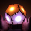
In case you missed it, here are the results: magazine image, crochet tablecloth, and miscellaneous electronics.
The specs of the system are listed in the table above. I tried imaging with both a 28mm and 50mm focal length lens. I estimated the best possible resolution of the system based on the diffraction limit (around 6μm). It is actually difficult to test this experimentally without a high resolution target. I tried printing a vector file listed on this large format photography forum, but I was limited by my printer resolution. The best I could determine with this printout was that the system had resolution <40μm. I also looked for small, isolated features on the samples. The smallest feature in the print from the magazine is the ink spot, which I estimated to also be about 40μm, so I couldn't use it to get a better estimate for the resolution. There were small divots in the electronics that were pretty well isolated. Because I knew the field-of-view, I could count the number of pixels taking up the small divot to get an estimate of the resolution, about 10-15μm.
Overall, I was happy with the performance of the system, but I have a few notes in case you want to try this project out.
Stability of the stage: Firstly, get high quality linear stage components. The components I used had way more play than I thought they would. I only used one of the slider mounts in the the kit for each rod, so maybe that was why the stage didn't feel very stable. The stage worked well enough for me, but this would become more of an issue for higher magnification systems.
Optics for higher resolution: The same idea can be used for higher magnification microscopes. However, smaller motors with finer step size will be required. For example, a 20X magnification with this dSLR would result in a field-of-view of 1mm (if the microscope can image that large a system without vignetting). Electronupdate used stepper motors from a CD player in a nice build for a higher magnification microscope. Another tradeoff will be shallow depth of field, which means the imaging will be limited to thin samples and you will need finer translation mechanism in the z-direction.
Stability of the tripod: This system would work better with a more stable camera mount. The lens system is heavy and the tripod is tilted 90deg from the position for which it is designed. I had to tape down the feet of the tripod to help with stability. The shutter could also shake the camera enough to blur the images.

Participated in the
Arduino Contest 2019


![Tim's Mechanical Spider Leg [LU9685-20CU]](https://content.instructables.com/FFB/5R4I/LVKZ6G6R/FFB5R4ILVKZ6G6R.png?auto=webp&crop=1.2%3A1&frame=1&width=306)


