

Introduction: RC Car Lap Timer


My Son has recently got into Radio Controlled (RC) Cars and likes to time himself when he practices so that he can improve his driving. It's easy for him when I'm about and can time his lap but when I'm not about he uses his phone stopwatch. This is not ideal because he wants to put all his concentration into driving his best lap time.
I like to build electronics projects for fun and my day job is a freelance industrial controls engineer so I thought it would be easy to make a lap timer using components I had in my workshop. I forced myself to work with two constraints. Firstly, I didn't want to buy anything in and wanted to make exclusively with materials I already had immediately available to hand. Secondly, I didn't look online at any previous designs hopefully forcing me to be more creative with my ideas.
The display was an easy choice as I only had LCD displays in my electronics box. I wanted to use a simple sensor to start and stop the timer. I decided that the best option wouldn't have any physical contact with the car. I looked in my various boxes and found I had IR sensors, Capacitive Proximity Sensors, Inductive Proximity Sensors, and Simple Light Dependant Resistors (LDR). The proximity sensors required the RC Car to get really close, the IR sensor was pretty good but I decided the LDR was the best option as they are really very cheap and I most people who have bought a basic electronics kit have probably got one lying around somewhere.
Supplies


I used Supplies I already had in stock but you could easily swap out what I used for other materials that you already have. Here's what I used:
Timer And Display:
- Arduino Nano (could use any other Arduino dev board)
- Light Dependant Resistor
- LED
- Spring Return Push Button x 2
- PCB, Breadboard or Prototyping Board
- Enclosures
- 20mm PVC Conduit
- 20mm PVC Conduit Adaptor
- On / Off Switch
- 16 x 2 LCD Screen
- I2C LCD Screen Backpack
- Header pins 15 pin x 2
- 18650 Lithium Battery x 1
- 18650 battery holder x 1
- TP4056 USB 18650 charge controller x 1
- MT3608 Boost Converter x 1
- 5mm PCB Screw Terminals x 20
- Rocker switch for power x 1
- 12mm diameter passive buzzer x 1
- Jumper Wires
- Solder
Light Source:
- Lens From Torch or any other Convex Lens
- Ultra bright LED (taken from torch)
- 5mm PCB Screw Terminals x 20
- PCB, Breadboard or Prototyping Board
- Jumper Wires
- 2-Core Cable
- 18650 Lithium Battery
- 18650 battery holder
- TP4056 USB 18650 charge controller
- Toggle Switch
- Enclosure
- 32mm PVC Waste Pipe
- 25mm Conduit Adaptors x 2
- Adhesive Tape
Tools:
- Soldering Iron
- M4 Tap
- Laser Cutter
- 3D Printer
- PC or Laptop
- Screwdrivers, pliers, cutters etc.
Step 1: Timer Electronics


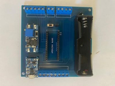
For the electronics I reused a PCB I had designed for a previous project. I designed this PCB intentionally so that it could be used for other projects so I made sure I had connections for plenty of analogue and digital pins as well as communication protocols such as I2C and SPI. Details of this PCB can be found here Arduino Games Console - With Multiple Games : 6 Steps (with Pictures) - Instructables.
You do not need to build a PCB for this project as it will work just as well if you build it on a breadboard or prototyping board. In the pictures there is a schematic diagram showing you what you need to connect if you just want to build with the minimum necessary components.
The heart of the electronics design is the LDR starting and stopping the timer. I have included a YouTube video detailing how the LDR works as a voltage divider. The LDR is simply pushed into a rubber tap (faucet) washer which is then pushed into a piece of PVC conduit to act as a light shroud. The light source points the light down the conduit at the LDR. When the car passes in front of the light source it changes the resistance on the LDR starting the timer. When the RC car passes through the light beam again it stops the timer. Take a look at the YouTube video I have created to see how the LDR is used with the Arduino to start and stop the lap timer.
I used an Arduino Nano however any of the other Arduino development boards would work fine and it wouldn't be too hard at all if you wanted to do the project with a PIC Microcontroller or other microcontroller.
For the Arduino code I simply repurposed the debounce example that is included in the Arduino IDE. I adapted it to include the I2C LCD and used the LDR to trigger a variable at a threshold value which starts and stops the timer. I've include the sketch if you want to use it.
Attachments

Step 2: Light Beam


I made the light beam out of a broken high powered torch (flashlight). I used the High powered LED and the lens.
A small piece of 32mm Waste pipe is used as the body of the light source. The torch Lens is mounted on a piece of 25mm electrical conduit adaptor this can slide up and down the body so that a really tight light beam can be focused on the LDR. The high powered LED is also mounted in a 25mm conduit adaptor which is also then pushed up the 32mm waste pipe.
The electronics is very simple. Its simply an 03962A charge module charging an 18650 battery which powers a high powered LED taken from a torch. The simple schematic shows how the light source is connected together.
Step 3: Enclosure & LCD Bezel

The enclosure was made using laser cut 3mm plywood. I use an online tool called makercase.com to design boxes for me. This is an excellent resource for saving time when designing laser cut boxes as it does much of the hard work for you. Once you've designed to outside of your box you can then download the CAD files and then use the 2D CAD package of your choice to add any cut outs for buttons etc. AutoCAD LT is the type of CAD package ideal for adding all the extras to the enclosure. I tend to ensure I use different drawing layers for the outline to be cut, the text and any engravings so that when you open the drawing on the laser cutter software you can set the laser power up for the different layers together with the order in which you want to cut or engrave, for example you normally want to engrave any images or text before you cut so that the material doesn't move.
The 4 screws in the corner of the box pull the box tight together so there is no need to glue the box. I did this partly because I wanted the console to be repairable and modifiable in the future. The bottom hole is cut to 3.5mm and then treaded with a 4mm tap as shown in the image.
The bezel really tidies up projects that use LCD screens. I designed it using Fusion360 then 3D printed it using my Ender 3.
The bezel is attached to the enclosure using strong double sided tape.
I have included the STL file for anyone who wants to 3D print their own LCD bezel.
The enclose CAD file is attached if you want to use it.
Attachments
Step 4: Testing
Next we tested our Lap Timer using my sons stunning Tamiya McLaren Senna TT02 RC car and it all worked just as expected!

![Tim's Mechanical Spider Leg [LU9685-20CU]](https://content.instructables.com/FFB/5R4I/LVKZ6G6R/FFB5R4ILVKZ6G6R.png?auto=webp&crop=1.2%3A1&frame=1&width=306)


