

Introduction: RC Airplane: Shark Style!


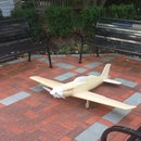
The ParkShark is the master of its environment. Capable of blistering speed and extreme maneuverability it is able to pray on the unsuspecting. It is an airplane that is sure to attract lots of attention wherever it is flown. Is the attention because it fly's exceptionally well, its devilishly good looks, or is it because its actually ridiculous? The verdict is not in yet but today you can learn to build your own!
The ParkShark was born from the elemental desire to go faster, be more agile, and look even better doing it. This shark is fast (60+ mph) and has significantly control authority for extreme maneuverability. Although, not a true acrobatic airplane it is an exceptional bank and yank type airplane, but also tracks and glides well. I hope you can have as much fun building an flying this as I do, so lets get started.
Step 1: Tools and Materials Required
The ParkShark is constructed similar to a parkjet made from depron. For this reason the aircraft is very quick to build (ie. a couple of evenings) and does not require many tools or material to build. Listed below are the materials required to build the airplane.
Materials
- 5 Minute Epoxy
- Hot Glue
- Thin CA
- 6mm Depron
- I recommend using white depron, it is harder and more durable than the gray depron. I only used gray depron because it was laying around from another project.
- 1/8" thick Plywood
- 4 Control Horns
- 1/32" thick Basswood
- 4 Small Screws (for the motor)
- 4 Small Neodymium Magnets
- Velcro
- Music Wire of assorted sizes
- Nylon Thread
- Hinge Tape
Tools
- Razor Saw
- X-Acto Knife
- Razor
- Cutting Matt
- Sanding Block
- Drill & Bts
- Pins
- Needle Nose Pliers
- Screwdriver
- Straight Edge
Step 2: Electronics Selection
The ParkShark is designed to be a 4 channel airplane, meaning that it will have four control inputs. These include throttle, aileron for roll, elevator for pitch, and rudder for yaw. It is made for electric power and below are the components required.
Electronics
- Transmitter- Your choice of a transmitter with at least 4 channels,
- I used a Futaba 8J
- Receiver- Your choice depending on the transmitter, it should be a "full range" receiver though.
- Motor- Turnigy D3536/5 1450kv motor or equivalent.
- ESC- 50 amp Hobbyking Blue Series
- Propeller- Master Airscrew 9x6
- Servos- 4 9g servos are required. Turnigy TG9e are a good fit.
- Battery- 3 cell 2200mah at least 25C
Step 3: Cost Estimate
Building the ParkShark is a relitively cheap project for the level of performance that it offers. I will exclude the cost of the transmitter and receiver from the price estimate because they vary so much by brand.
- Hobbyking 50amp Blue Series ESC: $24.75
- Turnigy D3536-5 1450kv Motor: $18.20
- Turnigy TG9e: $2.34 x 4 = $9.36
- 6mm white depron 13x39" $4.49 x 3 = 13.47
- Master Airscrew 9x6 $1.99
- Miscellaneous hardware $15
- Paint approximately $5
Total price excluding transmitter and receiver $87.77
Step 4: Plans


The plans for the park shark are slightly different from the shark that I have constructed. I will try to point out the differences during the steps. Their are two main differences. First slots are included in the fuselage for the vertical tail to mount into. Second the wing on the plan is shifted slightly forward of where it is on mine to correct the CG issues caused by using such a heavy/awesome motor.
The plans are sized to be printed on legal paper (8.5x14") to reduce the number of sheets that must be taped together. Conveniently it is also the perfect size paper to use for plans on 13x39" sheets of depron.

Step 5: Cutting Pieces


Depron is very easy to work with and cut, but only with a very sharp knife. It is important to us multiple passes to cut out the pieces to prevent the bottom of the cut from tearing. The plans can either be attached to the depron with double sided tape and cut around, or traced on to the board and cut. Cut on all of the solid lines, the dotted lines are reference lines to show the position of the pieces once assembled.
Step 6: Upper Fuselage Assembly


The upper fuselage forms the major structure of the airplane. It is important to make all of the glue joints a tight fit before gluing, to increase the strength and reduce the weight of the glue used.
Assembly
- Bevel the edge of the two upper side panels, such that when wrapped around the curve of the deck the joint is flush. It is approximately a 45 degree angle.
- UsE 5 minute epoxy to glue the edges of the panel in place.
- It will be impossible to glue the entire edge unless you have someone help you to hold it in place. Therefore I recommend using pins to help hold the panel in place, and also doing the front half then the rear half.
- Glue the other side in place.
- Once the epoxy has set use a sanding bar level the top of both side panels. This will allow the upper fuselage to simply be glued on top.
- Use 5 minute epoxy to glue the vertical tail into the slots in the deck, using a small square or triangle to ensure it is vertical.
- Sand a 45 degree bevel onto the rudder. This will allow to rudder to rotate.
- Glue the 1/32" basswood reinforcement and the control horn onto the lower edge of the rudder. Make sure the control horn will be parallel to the deck, not the hinge line.
Step 7: Building Pushrods


The pushrods used on the rudder and the elevator are both made from carbon fiber rods to reduce weight. The ends of the rods have wire Z-bends to connect to the control horns. This section will teach you how to make these pushrods.
Making Carbon Pushrods
- Find the size music wire that is a tight fit for the control horn and the servo arm, and cut a piece of each approximately 1.5 inches long.
- Bend the wire in to a Z-shape using needle nose pliers.
- Slide the Z onto the control arm of the servo.
- Using the nylon thread wrap the wire Z to the carbon pushrod. It may be helpful to put a drop of thin CA on the first couple raps, to help hold it in place while rapping.
- Finish rapping the Z onto the carbon rod, then carefully apply CA to the tread to permanently attach it.
- Cut the carbon push rod to length and repeat the rapping on the control horn side.
- Verify that the servo's control arm is centered.
- Glue the servo into the airframe using 5 minute epoxy. Don't worry the epoxy will come off of the servo if you scrape it with a razor
Step 8: Closing the Upper Deck


Now the the rudder servo is installed in the upper fuselage the upper deck can be covered. Note that there is not a piece for the hatch included in the plans because every aircraft will be slightly different since it is built with out bulkheads.
Upper Paneling Installation
- Use 5 minute epoxy to glue the rear deck lid to the side panels and to the vertical tail and tail fin. Pins can again be used to help hold this in position while the glue drys
- Repeat the same process with the forward deck lid being sure to keep the nose symmetric
- Install the hatch plate on the underside of the rear deck lid. This will be later to hold the magnets that secure the hatch in flight
- Use a sanding block round the edges the deck lids
- Use hinge tape to tape the rudder into position.
Step 9: Elevator Installation


The elevator is installed the in the same manor as the rudder was.
Elevator Installation
- Bevel the edge of the elevator to a 45 degree angle to make the hinge.
- Use 5 minute epoxy to glue the control horn and 1/32" basswood reinforcement plate to the elevator.
- Fabricate the pushrod in the same manor as used on the rudder.
- Use hinge tape to tape the elevator on to the horizontal tail.
- Use 5 minute epoxy to glue the elevator servo into the underside of the deck.
Step 10: Wing Fabrication
There are always a number of options to consider when building a wing for an RC airplane. Among the most important are performance, and time to fabricate. Sadly with many traditional balsa building techniques as the performance increases so does the time to fabricate the wing. However, with some more modern techniques such as using hot wire cut foam wings, high perfomance airfoils can be made precisely and quickly. I know that not everyone will be have the tools to make a wing this way, so I will also describe how to build a wing using a flat sheet of depron.
Step 11: Hot Wire Cut Wing Fabrication


A hot wire cutter works by passing electricity through a thin wire with a high electrical resistance. This causes the wire to heat up rapidly. The hot wire can then be used to cleanly cut through foam and even cut airfoils into wings. For this airplane I selected the PSU 94-097 airfoil (PSU 94-097). It is capable of producing high lift at low drag at the airspeed and scale that radio control airplane operate at. Because this airfoil is cambered inverted flight will be limited. Unfortunately I do not have pictures of cutting out the wing core because that was done a couple years ago however a diagram has been included. Below are the steps used to achieve the result.
Hot Wire Cutting Wings
- Make the template for the airfoil. It can be made from nearly anything, but be careful with things that are conductive, melt, or burn. Pictures of airfoils can be found here (UIUC Airfoil Database). The pictures can then be cropped and scaled to the desired size in word, or similar programs.
- Sand the edge of the template progressing up to 600 grit sandpaper. The smoother it is the less the wire will drag.
- Using a pencil to coat the edge of the template with graphite, it will help the wire slide across it.
- The template can then be attached to the foam blank with double sided tape or hot glue.
- The hot wire bow is then guided across the template starting from the upper trailing edge and then working around the leading edge and back. Be sure to let the wire do the work and not to force it otherwise the leading edge will be scalloped.
Installing the Wing Spar
- Cut 4 pieces of 3/32" thick bass wood 1/2" wide and 18" long
- Then measure back from the leading edge 1.5 and 2 inches and draw a line across the wing. This marks the location of the cut outs for the wing spar.
- Use a razor to carefully score the foam long the location where the spar will be installed.
- Use a razor to add more scores where the spar will be glue, these aid in the removal of foam.
- Drag a flat head screw driver through the scored location of the spar to remove the foam.
- Verify the fit of the spar and if necessary remove more foam.
- With a hot glue gun apply a medium layer of glue into the channel and then quickly insert the bass wood spar.
From here on the fabrication process would be the same for a depron wing.
Step 12: Depron Wing Fabrication


A depron wing will provide a light weight and easy to construct wing with decent aerodynamic performance. The aircraft will land slightly faster than an airplane with a proper airfoil. Since I have not actually constructed this wing I have included some CAD pictures of what it would look like. Later in this Instructable the horizontal tail will be reinforced in this manor.
Depron Wing Fabrication
- Use the plans as a guide mark the location of the spar on the two wing blanks
- Cut a grove into the depron to fit the spar. It should be a carbon tube approximately 4mm in diameter.
- Use the tube to clean the foam out of the channel.
- With a mask, gloves, and safety glasses lightly sand the carbon tube.
- Cut the carbon tube to fit in each wing section using a razor saw.
- Note this will quickly dull the razor saw, I recommend keeping old saws on hand specifically for this.
- The carbon dust should be cleaned up immediately with a wet paper towel.
- Apply 5 minute epoxy to the channel and lay the carbon tube into position.
From this point forward the wing construction would be the same between the foam core wing and the balsa wing
Step 13: Joining Wing Halves


Since the wing was fabricated in two pieces in both the depron and foam wing they will need to be joined. This joint is critical because it has the highest stresses on it in flight.
Wing Joining
- Make sure the spar exposed in the inner 2 inches of each wing panel. This may require removing foam from the depron wing to expose the other side of the spar.
- Glue the two wing sections together with 5 minute epoxy.
- Cut out one 1/8x2x4 inch plywood plate fr the upper surface, and one 1/8x1x3 inch plywood plate for the under side of the the wing
- Verify that the plywood plates will fit flush with the spar and adjust the fit as necessary.
- Use 5 minute epoxy to glue the plates into the center of the wing.
Step 14: Wing Attachment


Wings do not attach to fuselages, fuselages hang from wings. That idea is why the wing carries through the fuselage of both designs.
Attaching the fuselage to the wing is as simple as applying 5 minute epoxy to the plywood joining plate and attaching it to the fuselage according to the drawing. Note that I also installed a brace to support the trailing edge.
Step 15: Assembly of the Lower Fuselage


The lower fuselage is assembled in the same manor as the upper fuselage was. The only challenge that will be faced in cutting the notch out of the side panel for the wing.
- Cut a small hole in the deck and feed the elevator servo wire into the upper fuselage.
- Sand a bevel on the upper surface of the side panels as was done on the upper panels.
- Test fit the side panels to determine the location of the notches required for the wing to be flush.
- Once the fit is perfect, use 5 minute epoxy to glue the side panels in place. Use pins as needed for extra support.
- Use a sanding block to sand the top of the panels flat.
- If desired you can make a trapezoid to fit in front of the wing so that the inside of the mouth looks more complete and doesn't have the innards exposed.
- Fit the lower sheeting to the fuselage with 5 minute epoxy.
- Sand the edges round.
- Lastly hot glue the dorsal fins on to the lower fuselage, being careful that they are aligned with the tail.
Step 16: Horizontal Tail Reinforcement


Because the depron is rather soft and flexible large unsupported pieces are able to flutter at high speeds. For anyone interested here is a short video link showing what flutter can do Aircraft Flutter. Since we don't want our tail to look like that it will be reinforced with a 3mm carbon tube.
Horizontal Tail Reinforcement
- Use a straight edge to mark the location that the tube will be placed.
- Use a razor to score the foam where the front and back of the tube will go.
- Score the foam a few more times between the front and rear marks.
- Run the end of the carbon tube through the scored foam to clear a channel for it to rest in.
- With a mask, gloves, and safety glasses on lightly sand the carbon tube to prepare it for gluing.
- Clean up any carbon dust immediately with a wet paper towel.
- Use 5 minute epoxy to glue the tube into the slot.
Step 17: Motor Installation


Mounting the motor is an important step in building the airplane, since it is a bad day for when the motor decides to leave the airplane in flight. Below is how to make sure its always firmly attached.
Motor Installation
- Verify that the front of the upper fuselage is square. If necessary correct it with a sanding bar.
- Cut out the motor mounting plate from 1/8" plywood.
- Mark the location of the motor mounting screws on the plate.
- Drill a small pilot hole for the motor screws to prevent the plate from splitting.
- Apply a dab of thread lock blue on the screw threads and mount the motor to the firewall.
- Use 5 minute epoxy to glue the firewall to the upper fuselage and deck.
- Sand the firewall to be flush with the fuselage.
- Add a little more epoxy to the outside of the firewall where it meets the foam fuselage to give it a little more to grab to.
Step 18: Aileron Fabrication and Installation


For an airplane of this type the ailerons can either be made from balsa or from depron. Since my wing was made from blue foam which is softer than depron I chose to make them from balsa. However, if the wing was made from depron just using a piece of depron with the basswood control horn reinforcements like used on the tail would have been completely okay.
Balsa Ailerons
- Cut out two pieces of balsa that are 14x1-1/2x1/4".
- Use a razor to give them a rough trailing edge shape.
- Use a sanding bar to finish sanding to shape.
- Use a sanding bar to sand a 45 degree angle into the leading edge of the aileron just like was done on the tail.
- Apply 5 minute epoxy to the control horn and attach it directly to the aileron.
- Cut the tips of the ailerons at the angle to fit in the wing.
Once the ailerons were made from either construction technique they can be attached with hinge tape.
Step 19: Aileron Servo Installation


The aileron servos can be installed the same way in both the hot wire cut wing as well as the depron wing.
Aileron Installation
- Mark the location the servos will be installed.
- Note if you are using wire pushrods like I did the servos should be positioned perpendicular to the hinge line. This minimizes the side load on the servo and control horn.
- The wire rods and be replaced with ball linkages for a cleaner set up with the servos located parallel to the nose.
- Cut out around the edge of the servo.
- If the wing is depron you can cut the whole way through.
- If the wing is thicker cut additional scores into the wing, and then remove the foam with a screwdriver.
- Test fit the servo in the pocket and adjust as required.
- Bend the pushrod as shown in the third picture. The zig-zag in the middle allows the length of the push rod to be finely tuned.
- Use 5 minuted epoxy to glue the servo into the wing.
Step 20: Battery Hatch Installation


Having a hatch that is easily removable and provides access to the battery and electronics makes for a much more practical airplane. I like to use small neodymium magnets to secure canopies because they have a strong hold and are not exposed on the exterior of the airplane.
Battery hatch Installation
- Cut a piece of depron the length of the opening on the top of the airplane. It is preferable to have it wider than the hatch needs to be.
- Glue the front doubler to the hatch blank. This piece will slide under the upper part of the forward fuslage and lock the front of the hatch in place.
- Use a drill bit the size of your magnet to gently drill a hole the dept of the magnet on the upper rear fuselage
- Use 5 minute epoxy to glue the magnets in place.
- Apply a piece of scotch tape over the magnets.
- Once the epoxy has cured place the canopy side of the magnet on the fuselage magnet. Then press the canopy down onto the magnets. This will leave an impression on the foam of where the magnets must go.
- Again gently drill a hole the deep of the magnet into the canopy.
- Use 5 minute epoxy and scotch tape to secure the magnet into the canopy.
- With the canopy in place sand the edges to match the fuselage.
Step 21: Painting


Painting is not really a required step, but will definitely make the airplane look a lot more finished. It will add a little bit of weight to the airplane, so it is up to you to decide if it is worth it. Otherwise you can always color the airplane with a sharpie for no weight penalty. Always test your specific paint on a scrap piece of foam first, some paints and spray propellants will dissolve foam.
I will not claim to be much of an artist. My goal of painting the shark was to make it look more refined and also to show off the fact it is a shark. I wanted to have the bottom of the shark lighter than the top, and to have the rear of all the fins and wings be lighter than the leading edge. Lastly and most importantly, it needed eyes so it can see where it is going.
Paints Used
- Craft Smart Red premium Satin Acrylic
- Craft Smart Black premium Satin Acrylic
- Craft Smart White premium Satin Acrylic
- FolkArt Cayman Blue Acrylic
Painting
- Start with the lightest color paint apply a base coat only where needed.
- While the lighter color is still wet begin painting with the darker color.
- Blend the lighter and darker paints together to create a smooth fade.
- Once the fuselage and wing are painted paint the teeth and eyes white.
- Paint the inner part of the eyes black and paint the eyebrows
Step 22: Tongue Installation


What kinda shark would fly without its tongue sticking out, not this one of course.
Tongue Installation
- Cut out a tongue of your liking from depron and sand it to shape
- Paint the tongue.
- Use hot glue to glue the tongue inplace
Step 23: Conclusion


I am very pleased with how the build turned out. The ParkShark looks sharp and flies superbly. This is an very good airplane for someone with some RC aircraft experience looking to have a great flying and head turning airplane.
For all of you good people who have supported my efforts on my other Instructable (Designing and Building Beautiful RC Airplane) I posted a few pictures of the two hanger mates together. I greatly appreciate the great community here and will be sure to post videos from the next time these airplanes fly.
I hope that you all have enjoyed this Instructable, and that some of you will use it to make your very own ParkShark. If you do build your own please post a picture of it in the comments, it would be awesome to see the work of other people in the community. Please post any questions and comments on this, and I will try to get back to you as soon as I can.

Grand Prize in the
Things That Fly Challenge

Participated in the
Move It

Participated in the
Mind for Design

![Tim's Mechanical Spider Leg [LU9685-20CU]](https://content.instructables.com/FFB/5R4I/LVKZ6G6R/FFB5R4ILVKZ6G6R.png?auto=webp&crop=1.2%3A1&frame=1&width=306)


