

Introduction: Geneva Clock


Our youngest son sent me a video of a wrist watch that he found interesting and wanted to know if I could explain to him how it worked. Well that would be too easy (for my ego at least, or maybe I'm just being played? ), so instead of simply explaining it to him, I decided to show him by designing, 3D printing, assembling and programming "Geneva Clock".
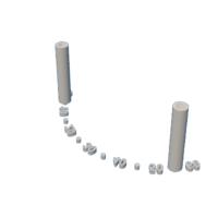
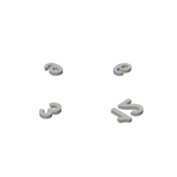
I had never seen a wrist watch or clock mechanism utilizing a Geneva wheel in this manner yet apparently there are quite a few wrist watches that do. Watches such as these incorporate three Geneva wheels with each wheel containing four digits; the first wheel containing the digits 1, 4, 7 and 10, the second containing the digits 2, 5, 8 and 11, and the third containing the digits 3, 6, 9 and 12. A "standard" Geneva wheel utilizes a fixed position rotating cam that rotates a fixed position rotating Geneva wheel. However, in these mechanisms the Geneva wheels are rotated around a fixed cam, and with the staggered digit patterns on each wheel, as the mechanism rotates, the digits appear in proper order around the face of a clock from 1 through 12.
This model utilizes a mechanism quite similar to the watch designs but is powered by a stepper motor, which in turn is powered by a stepper motor controller driven by an Adafruit Feather Huzzah32 processor. The model software is designed to home the clock to 12:00 upon power on or reset, obtain the current time via an NTP time server, then seek the current time. To accomplish NTP time acquisition, the clock uses a wifi connection via a network ssid and password entered by the user via a smartphone or other wifi connected device, avoiding the need to change the source code and download the changes to the processor.
Anyway, Marc, I hope you like your new "Geneva Clock"!
As usual, I probably forgot a file or two or who knows what else, so if you have any questions, please do not hesitate to ask as I do make plenty of mistakes.
Designed using Autodesk Fusion 360, sliced using Ultimaker Cura 4.12.1, 3D printed in PLA on Ultimaker S5s and an Ultimaker 3e, and programmed using the Arduino environment.
Supplies
Soldering iron and solder.
Thick (1/4") double sided tape.
AWG28 stranded wire.
Thick cyanoacrylate glue.
Step 1: Parts.
I acquired the following parts:
- One Adafruit Feather Huzzah32 (https://www.adafruit.com/product/3405).
- One Stepper motor kit (https://www.amazon.com/HiLetgo-ULN2003-28BYJ-48-Stepper-4-phase/dp/B00LPK0E5A/ref=sr_1_1_sspa?crid=7M7SZGW0ACNV&keywords=arduino+stepper+motor&qid=1704319819&s=electronics&sprefix=arduino+stepper%2Celectronics%2C116&sr=1-1-spons&sp_csd=d2lkZ2V0TmFtZT1zcF9hdGY&psc=1)
- One LiPo battery (optional, https://www.adafruit.com/product/1570).
- One 2mm diameter by 14mm long reed switch (https://www.amazon.com/dp/B07RS2M9TR?ref=ppx_yo2ov_dt_b_product_details&th=1).
- Five 6mm diameter by 2mm thick neodymium magnets.
I 3D printed the following parts at .15mm layer height, 20% infill and no supports unless noted otherwise:
- One "Back.stl".
- Four "Bolt (M8 by 1.25 by 12).stl".
- Two "Bolt, Motor.stl".
- One "Bracket.stl".
- One "Cam.stl".
- One "Cover.stl".
- One "Face.3mf".
- One "Gear (1.5m 8t).stl".
- One "Gear (1.5m 32t).stl".
- One "Geneva 1.3mf".
- One "Geneva 1.stl".
- One "Geneva 2.3mf".
- One "Geneva 2.stl".
- One "Geneva 3.3mf".
- One "Geneva 3.stl".
- Three "Geneva Axle.stl".
- One "Read Mount Cover.stl".
- One "Reed Mount.stl".
- One "Stand.stl".
- One "Wifi Wand.stl".
Not listed in the 3D printed components above but included in the files are the individual .stl files used to make the .3mf (dual extrusion) components.
This is a precision 3D print and assembly model using at times very small precision parts in very tight spaces. Prior to assembly, test fit and trim, file, sand, polish, etc. all parts as necessary for smooth movement of moving surfaces, and tight fit for non moving surfaces. Depending on you printer, your printer settings and the colors you chose, more or less trimming, filing, sanding and/or polishing may be required. Carefully file all edges that contacted the build plate to make absolutely certain that all build plate "ooze" is removed and that all edges are smooth. I used small jewelers files and plenty of patience to perform this step.
The model also uses threaded assembly thus an M8 by 1.25 and an M4 by .7 tap and die will assist with thread cleaning if necessary.
Attachments
 Back.stl
- Bolt (M8 by 1.25 by 12).stl
- Bolt, Motor.stl
- Bracket.stl
- Cam.stl
- Cover.stl
- Face Black.stl
- Face White.stl
- Face.3mf
- Gear (1.5m 8t).stl
- Gear (1.5m 32t).stl
- Geneva 1 Black.stl
- Geneva 1 White.stl
- Geneva 1.3mf
- Geneva 1.stl
- Geneva 2 Black.stl
- Geneva 2 White.stl
- Geneva 2.3mf
- Geneva 2.stl
- Geneva 3 Black.stl
- Geneva 3 White.stl
- Geneva 3.3mf
- Geneva 3.stl
- Geneva Axle.stl
- Reed Mount Cover.stl
- Reed Mount.stl
- Stand.stl
- Wifi Wand.stl


Step 2: Wiring.


To wire the clock, I performed the following steps:
- Using double sided tape, taped the esp32 to the stepper controller as shown.
- On the bottom side of the boards, soldered a black wire between the esp32 "GND" pin and the stepper controller "-" pin.
- On the bottom side of the boards, soldered a red wire between the esp32 "USB" pin (if you plan to use the optional battery, solder this wire to the esp32 "BAT" pin) and the stepper controller "+" pin.
- On the bottom side of the boards, soldered a yellow wire between the esp32 "A0" pin and the stepper controller "IN1" pin.
- On the bottom side of the boards, soldered a yellow wire between the esp32 "A1" pin and the stepper controller "IN2" pin.
- On the bottom side of the boards, soldered a yellow wire between the esp32 "A5" pin and the stepper controller "IN3" pin.
- On the bottom side of the boards, soldered a yellow wire between the esp32 "21" pin and the stepper controller "IN4" pin.
- On the top side of the esp32 board, soldered a 254mm length of wire to the esp32 "27" pin leaving the remaining end free for the time being.
- On the top side of the esp32 board, soldered a 254mm length of wire to the esp32 "GND" pin leaving the remaining end free for the time being.
- Pressed "Back.stl" into "Stand.stl".
- Removed the protective covering from the double sided tape then pressed the boards into position on the stand as shown.
- Slid the stepper motor wires through the front of the stand motor pocket then pressed the stepper motor into the motor pocket and secured in place with two "Bolt, Motor.stl".
- Plugged the stepper motor wire connector into the stepper controller connector.
- Tucked the excess stepper motor wires into the rear of the motor pocket.
- Slid the 245mm wires up through the top back motor pocket hole then out the hole in the back arm slot.
Step 3: Assembly.


To assemble the clock, I performed the following steps:
- Pressed "Gear (1.5m 8t).stl" onto the stepper motor shaft.
- Glued "Gear (1.5m 32t).stl" onto "Bracket.stl" such that the bracket towers are opposite the gear teeth.
- Positioned the bracket assembly onto the back assembly with one arm straight up.
- Placed "Cam.stl" onto the back assembly making certain the small key on the back was inserted into the small slot on the cam.
- Secured the cam to the back assembly using one "Bolt (M8 by 1.25 by 12).stl".
- Secured "Reed Mount.stl" to arm the slot on the back assembly using one "Bolt (M8 by 1.25 by 12).stl".
- Slid each of the 254mm wires up from the bottom of the reed mount and out the top, carefully bent the reed switch lead wires, then soldered each of the two 254mm wire ends to each of the two reed switch leads.
- Carefully slid the reed switch into the top of the reed mount then secured in place with "Reed Mount Cover.stl".
- Glued "Geneva 1.3mf" to "Geneva 1.stl" aligning the key in the .3mf component with the slot in the .stl component.
- Repeated the previous step for the remaining two geneva wheels.
- Pressed two magnets into the Geneva 2 wheel magnet pocket.
- Secured the three Geneva wheels to the bracket assembly using three "Geneva Axle.stl" noting the positions of the 10, 11 and 12 positions of each wheel.
- Secured "Face.3mf" to the back assembly using two "Bolt (M8 by 1.25 by 12).stl".
- Pressed one magnet into the stand magnet pocket.
- Pressed one magnet into "Cover.stl" such that the cover magnet matches the polarity of the stand magnet.
- Magnetically attached the cover to the stand.
- Pressed one magnet into "Wifi Wand.stl".
- Attached the wand to the stand.
Step 4: Software.


Prior to programming the clock, I connected the esp32 USB port to my computer USB port, and when using the battery backup option, plugged the battery into the esp32 battery connector.
I used the Arduino environment to design and test the attached file "GenevaClock.ino", so after starting the Arduino application, I loaded "GenevaClock.ino" then selected the board type (Adafruit ESP32 Feather) and the port number.
With the Arduino environment prepared and "GenevaClock.ini" software loaded, I set the software constant "HOME_SWITCH_CALIBRATE" to true, then downloaded the software to the esp32 board, ensuring the clock was rotating clockwise (if not, toggle the software constant "MOTOR_REVERSE" from true to false if currently true, or from false to true if currently false, then compile and download again) then performed the following steps:
- Waited until the clock 12 disk stopped near the face 0 digit. If it did not stop, I adjusted the reed switch mount closer to the digit wheels and repeated this step (this may take a few times) until it stopped.
- Once stopped, I carefully examined the location of the 12 disk for being centered on the face 0 digit. If it 12 disk was not centered on the face 0 digit, I made a small adjustment to the reed switch holder, pressed the esp32 reset button, and repeated this step until the 12 disk was centered on the face 0 digit.
- Once the 12 disk was centered on the face 0 digit, I glued the reed switch holder to the back.
With the clock homed, I set the software constant "HOME_SWITCH_CALIBRATE" to false, downloaded the software to the esp32 board, waited for the clock to move well beyond the home position (e.g. 1:00), then performed the following steps:
- Magnetically attached the wifi wand to the outer lead of the reed switch.
- Pressed the esp32 reset button.
- When the esp32 onboard red led began to flash, immediately removed the wifi wand.
- With the wifi wand removed, observed the onboard red led stopped blinking.
- Opened my phone's wifi settings.
- Selected the "Geneva Clock" network to connect to.
- Waited for the wifi manager app to appear.
- Using the wifi manager app, I entered the wifi network (ssid) and password for the wifi network I want the clock to connect to.
- Pressed save on the wifi manager app.
Once saved, the clock homed, then rotated to the correct time.
And that is how I 3D printed, assembled and programmed "Geneva Clock".
I hope you enjoyed it!
Attachments

Runner Up in the
Anything Goes Contest


