

Introduction: Electric Bulb Shaped Neon Led Lamp


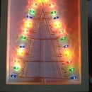
I had some left-over neon led strip and I stumbled upon this excellent tutorial on how to make neon signs, and especially the 3D printed frame, using Fusion 360.
More-over my parents in law recently gave me what could be used as a lamp base, so I decided to build a lamp.
My neon led is non adressable, simply R,G,B and I wanted the lamp to be used with or without a led controller, so I chose to use 3 switches in order to either select one of 7 colors via a switch position, or use a led controller such as the Tuya led controller I'm using on another led sign.
Supplies
You'll need:
- a flexible 12V neon led strip
- 3 switches
- a barrel power connector
- electric wire
- a piece of 4-pin female connector
- a 12V 1A power supply
- a 3D printer
- something to make the lamp base
- super glue
- hot glue gun
- clear silicon
- optional, an RGB Led controller such as this one.
Step 1: Design and Print the Lamp
I designed the lamp according to this tutorial, since I liked its shape.
I however modified to bottom of the lamp, so that it can be mounted on top of the tube of the lamp base.
So you'll likely have to modify it. I've included the Fusion360 source file to the project files, as well as my STL for reference.


Step 2: Print the Switch Cover
I printed the switch cover in transparent PLA, this led to an interesting idea detailed in the next chapters.
I attached the Fusion360 source and STL files to the project.


Step 3: Carve the Base


I wanted the power connector and barrel jack to be at the back of the base, and the switches at the front.
So I drew a template on the base and used a Dremmel router to carve it, taking care to make relatively shallow passes (a few mm each pass). The dimensions of the hole for the switches must be slightly less than the switch cover.
I realized that I had a few spare leds and that having a glowing button cover would be cool. So I carved a place to put a section of 3 LED in front of the switches.
Step 4: Soldering


This is the most tedious step, since there is not much room.
I used a needle nose pliers to hold the wires while soldering them.
I joined the schematic, it's pretty simple.
The neon led ribbon is a common anode type, so the 12V supply is fed directly to the ribbons, from the barrel jack and the 4-pin connector.
The ground connections of the ribbons are groing to the center pin of the switches.
The "up position" (hence "down" pin) of the switches is going to the ground of the barrel jack via a common wire (since I want a switch up to light-up the ribbon with the power coming from the barrel connector).
The "down position" of the the switches is going to the ground pins of the 4-pin connector
I recommend to completely wire one circuit (switch) and test it before soldering the other ones.
The 4-pin connector is separated from the wooden base by a spacer. I used a piece of PCB stuck with super glue.
I used hot glue to help maintain the barrel connector and the wires while soldering.
I removed the silicon cover from one segment of the neon led ribbon (3 leds) and put it next to the switches, oriented slightly upwards.
Then I filled the voids with clear silicon.
Step 5: Enjoy!


