

Introduction: NeoPixel Ring Lamp With a Circuit-Sculpture Style


This is the story of an abandonned clock project where the time was supposed to be shown using the position of 4 servo-driven micro hand-fans and illuminated by an addressable led strip, but...I blew-up too many micro-servos and got tired of the project.
So I resurrected it in the form of a 60 'NeoPixel' ring to show the time, keeping the original idea of having the circuit at the center of the device in the form of a 'dead-bug' or circuit-sculpture.
There are 2 switches to select:
- The transition type between minutes: A smooth transition or a twinkling effect transition
- The clockwise or anticlockwise movement of the clock, since all my clocks and watches are...anticlockwise.
There is a chase effect transition between hours, that is also clockwise or anticlockwise depending on the current clock direction.
A potentiometer allows for setting the brightness of the clock.
There is an auto-off feature, currently set to 10min, associated to a PIR presence sensor.
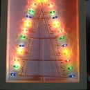
The current minute is shown by the white led, and the current hour is shown by the first red led. Indeed, the "rainbow" turns each hour, to follow the current hour. It does not move progressively like the hour hand of a clock. I thought time might be easier to read this way. Anyway It's quite easy to modify in the software (a minor change line 149 in fillLedsFromColorwheel() in order to shift the inital hue of the LED ring by a fraction of the current minutes).
I did not take enough pictures to make a full instructable but I thought it could be worth documenting it anyway.
You may want to go to the demo first.
Attachments

Supplies
You will need:
- An ATMega328P
- A Chronodot RTC Clock module
- A PIR Sensor
- A 60-LED WS2812 LED Ring
- 2 micro switches
- 1 22KOhms micro-potentiometer (or any value above 10KOhms)
- 1mm diameter brass rods
- 30mm 1mm diameter brass tube
- A micro-USB breakout board or any other type of 5v connector.
- A 100nF decoupling capacitor
- An Arduino or a USBasp Programmer in order to program the ATMega328P.
- You may want to add a Shottky diode to protect against power polarity inversions.
Step 1: Program the ATMega328

The ATMega328P I received is preset to run at 1MHz on its internal clock.
I needed it to run at 8MHz on its internal clock so I first used this Instructable to use the "burn bootloader" function using the board Atmega 328 on breadboard, and my USBasp programmer (you may also use another Arduino as an ISP Programmer).
Once this was done, I flashed the Blink sketch and checked that the intended output was flashing at 1Hz as expected.
Then I flashed the sketch (that I developped using an Arduino Micro since it's easier to have it directly plugged in USB).
You may also flash the sketch after assembly, but this does not allow for progressive testing while assembling.
However I had to fix a few bugs after assembly, so above is the clock connected to the USBasp programmer using micro-clips:
Attachments
Step 2: Circuit Assembly


The circuit assembly is the hard, but fun part.
All it really requires is patience.
I should have taken more photos, but...I did not intend to do an Instructable at first, only at the end did I realize that it might be worth sharing this project. Sorry about this.
Anyway, here are the main steps I followed:
I started by drawing the circuit on paper, and identifying the pins on the ATMega (I had chosen them in order to facilitate the assembly, when I had a choice).
Then I started by flattening the pins of the ATMega328, giving them only a slight angle (much like if it was going to be surface-mounted).
Then I soldered the 5v and GND wires, that run from the top of the LED Ring (soldered to the ring power supply pins), to past the bottom of the LED Ring, where the actual power connection will be. I hot-glued the wires to the bottom of the LED ring, since there is no connector to solder on here.
Then was the litteral centerpiece: The ATMega328.
I marked the center of the ring and the position of the ATMega with a black pen, on the brass rods.
I then figured-out that it would be much easier to glue the ATMega to the power brass rods and wait for the glue to cure before soldering its power connections. That's wat I did, with a mix of hot-glue and super-glue (but I used too much hot glue, that I needed to remove afterwards in order to be able to solder the power connections...).
Once glued, the easy and fun part commences.
It's only a matter of imagination, a bit of precision and care, to solder the various connections.
Here is the order I roughly followed:
I intended to do progressive testing, this makes life so much easier in case of trouble.
So I began by soldering the ATMega328 power connections and its 100nF decoupling capacitor, as well as the NeoPixel Ring's data-in line.
A general rule I follow when making circuit sculptures with brass rods:
I start by measuring each brass segment required, and I often mark bend positions with a black pen.
Then I cut and bend the wire as required.
Once it fits in the intended position, I add flux and solder to each solder position (on the brass segment I'm soldering and on the component pins). I presolder each connection point, then position the brass segment (usually with goose-neck pliers) and quickly solder the joints. I find this makes soldering much easier (solder flux is super-important here).
Once the power connections soldered, I soldered the Chronodot RTC module and the PIR sensor modules.
This was time for a first power-on test!
And it was OK, the clock was working as expected, albeit flickering due to the open brightness setting pin.
I scavenged a SMD 22 KOhms micro-potentiometer that fits nicely on top of the ATMega328. It's connected between the power rails and its cursor pin is connected to the intented analog pin. I also made a small pot handle using a piece of brass rod and a Dremmel grinder, that I super-glued in position.
At the top and bottom of the ATMega328 I placed the minute transition mode and direction micro-switches, connected one extremity pin to ground and the middle pin to the corresponding digital input pin.
Time for a final power-on test, which revealed a few bugs in the hour transition and auto wake-up code. It's nice to have the ICSP pins available in that case, even if sometimes not practical to connect to. But I did not want to wire an ICSP connector on this project (that's what I often do otherwise).
This clock is intended to be hung in my garage, but I wanted to be able to put it on a furniture as well, so I designed a small base using scrap wood, glued and stained.
Step 3: The Base


I wanted it to be easy to switch from the hung to standing position, I tought a sliding connector would do the job.
And indeed, it did.
So I first cut, glued, sanded and stained two pieces of wood in order to make the base of the clock.
Then I marked the center position and drilled two holes to accomodate two pieces of 2mm brass tube, acting as a female connector (with the same spacing as the clock's power wires, of course), at the end of which I soldered two small pieces of insulated wire going to the USB breakout board.
I like using these small micro-USB breakout boards to provide power connectors to my projects, so I machined a place in the base for this breakout board, using a Dremmel mini-router.
I did not place a diode to protect against power polarity inversion, but you may want to place a shottky diode in series with the VCC. I just made sure that when the USB socket is at the back of the stand, the GND connection is at the left.
Last step is a bit of hot glue in order to insulate the PCB and make sure it's fixed in position.
Time for a short demo! https://www.youtube.com/watch?v=woiIGEO7t_8
Step 4: Final Words

I might as well keep it in my living room, on my fireplace between my other circuit sculptures.

This is an entry in the
Making Time Contest


