

Introduction: PulseFit - DIY Heart Sensor With Auto-Adjusted Threshold and Heart-Shaped LED Heartbeat Indicator


I am a Biomedical Engineering (BME) graduate student at Purdue University. As a BME, I really enjoy making quick and easy projects that highlight some sort of physiological quantity. Heart rate is such an activity. There are numerous projects that deal with detecting a person's heart beat all over the internet. I wanted to put a little spin on such projects. I have created a heart beat detector that blinks an LED when a heart beat is detected. Oftentimes with these measurements, there is a bit of threshold adjustment that takes place when designing algorithms to calculate heart rate. In many DIY projects I have seen, the threshold is manually determined and is often tuned for each person. In my project, the threshold is automatically tuned so that the circuit does not have to be re-calibrated to each user. Again, pretty simple, but fun. Enjoy!
I will be updating this project. I think adding a nice enclosure and designing a printed circuit board to replace the breadboard design would be really nice. Feel free to follow the project on Hackaday.io if you would like to stay updated with my progress.
*****NOTE: This is NOT a medical device.
Step 1: Theory

*****NOTE: This is NOT a medical device.
When the heart pumps, the amount of blood to certain extremities, such as the fingers, increases. The amount of blood in a finger can be measured using a light emitter and light detector. The light shines through the finger and the detector measures the amount of light that passes through the finger. The amount of light that passes through the finger changes with the amount of blood in the finger and you get a very characteristic waveform.
Step 2: Overall Circuit Diagram

The circuit has a few major parts that we will explore in detail
1. IR LED
2. Photodiode
3. Transimpedance Amplifier
4. Band-pass filter
5. Threshold adjuster
6. Peak detector
7. Heart beat indicator
Parts list
1 x IR LED
1 x BPV22 Photodiode
2 x MCP6004 - General Purpose single supply amplifier, quad amplifier
1 x LM7805 - 5V regulator
1 x 1N4148 Diode
2 x 47 kOhm resistors
3 x 1 MOhm resistor
1 x 62 kOhm resistor
1 x 1 kOhm resistor
1 x 220 Ohm resistor
1 x 1.5 MOhm resistor
1 x 240 Ohm resistor
1 x 33 nF capacitor
1 x 570 nF capacitor
1 x 9V battery
22 x red LEDs
1 x perfboard
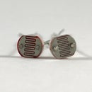
Step 3: Light Emitter (LED) and Detector (Photodiode) Pair

A light emitting diode (LED) and photodiode are often employed in heart monitor circuits. You are probably already familiar with light emitting diodes, you run an electrical current through them and they emit light. People may be less familiar with photodiodes. In short, a photodiode will produce current when it light hits it.
For our LED circuit, we will include a resistor to set the amount of current that will run through the LED so we can control its brightness.
When placing your finger between the LED and photodiode, remember to remain very still.
Go onto the next step to learn how to utilize the photodiode.
Step 4: Transimpedance Amplifier

A transimpedance amplifier is a type of circuit that converts a current to a voltage. We will use a transimpedance amplifier to convert the current from the photodiode to a voltage at the output of the amplifier. This happens because the current produced by the photodiode causes an equal and opposite current through Rf highlighted in the schematic. By controlling Rf we can control the voltage output of the amplifier with Ohm's Law (V = I*Rf). C1 in the feedback loop creates a low-pass filter with Rf with a cutoff frequency of 4.8 Hz. This filters out other signals that do not pertain to the pulse signal.
Step 5: Active High-pass Filter

A high-pass filter is a circuit that passes only high frequency signals. The high-pass filter we constructed (highlighted in picture) has a cutoff frequency of 0.56 Hz. The "active" part of the name means that our circuit has gain. It will not only pass signals above 0.56 Hz, it will also amplify these signals as the current from the photodiode is going to be really small.
Step 6: Peak Detector and Threshold Adjuster

The threshold adjuster is pretty straightforward. The signal from bandpass filter goes through a peak detector. A peak detector is a circuit that holds the peak voltage of an alternating current. Finding the peak voltage allows us to set the threshold for our heart beat detector by hardware design instead of using software. Using a peak detector in the design also allows us to avoid using any sort of manual thresholding using a potentiometer or something like that. Because there is a forward voltage drop across the diode, the voltage at the output of the peak detector will be a few milliVolts lower than the actual peak voltage. This is what we want. The capacitor at the output of the diode holds the peak voltage because a capacitor stores charge. The resistor in parallel with the capacitor ensures that our capacitor will not store a single peak voltage indefinitely, but will allow the peak detected to adjust with higher or lower pulse amplitudes due to stronger or weaker pulses, respectively.
Step 7: Comparator and LED Heartbeat Indicator

For the final part of our circuit, we will use a comparator. A comparator is a simple op amp circuit that compares (hence the name) the voltage from our pulse detector (output of the active band-pass filter) with the peak detector using subtraction V(pulse) - V(threshold). If V(pulse) is higher than V(threshold), the output of the comparator is 5V and our LEDs lights up indicating a heartbeat. If V(pulse) is lower than V(threshold) the output of the comparator is 0V (ground).
NOTE: The general equation for a comparator is Vout = V+ - V-, where Vout is the output voltage of the comparator, V+ is the voltage at the non-inverting pin, V- is the voltage at the inverting pin. Vout will either be V++ or V-- where V++ is the more positive supply of the op amp and V-- is the more negative supply. In our case, V(pulse) is V+, V(threshold) is V-, V++ is 5V, and V-- is 0V (ground).
Step 8: Assemble Your Heart Beat Indicator Circuit


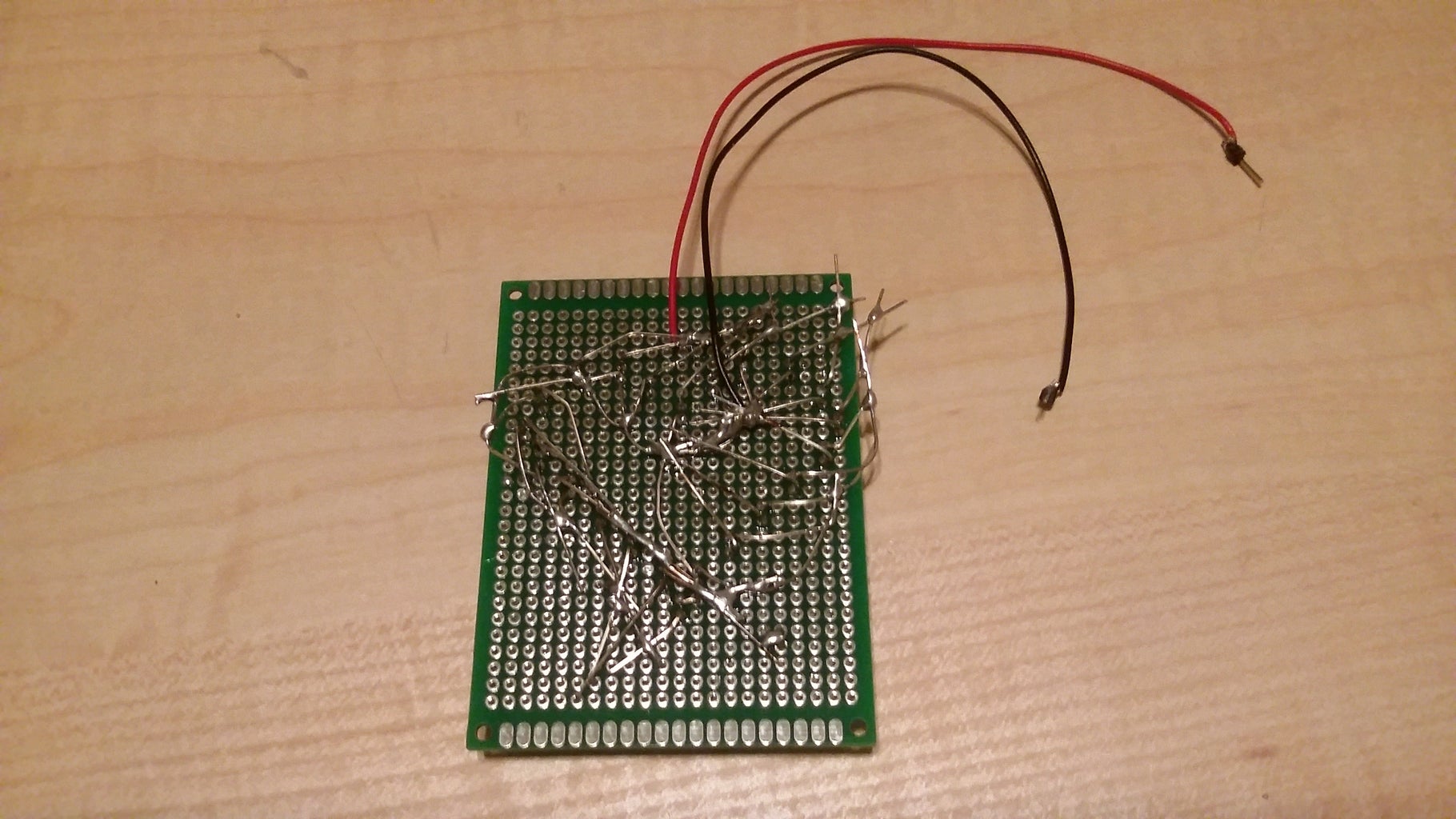


Feel free to be as creative with this as you want. I had a single LED heartbeat indicator, but then I decided to add a bit more to be fancy. I used 22 LEDs in parallel with each other (you want them in parallel, not series) and used a single series resistor to set the current. And, as you can see, arranged the LEDs in the shape of a heart! How fitting.
To do this, attach all the anodes (long legs of the LEDs) of the LEDs together. Do the same with the cathodes (short legs of the LEDs). Place a resistor at the output of the comparator and attach the resistor to the anode of the LEDs. Attach the cathode of the LEDs to ground.
Watch it blink with heartbeat!
I will be updating this project. I think adding a nice enclosure and designing a printed circuit board to replace the breadboard design would be really nice. Feel free to follow the project on Hackaday.io if you would like to stay updated with my progress.
As always comments and suggestions are welcomed!
Step 9: Showcase: As Seen on Adafruit Show-and-Tell

I was able to show-off PulseFit on Adafruit's Show-and-Tell a few times. Check out the videos.
Step 10: Showcase: PulseFit at Maker Faire Detroit!


I attended Maker Faire Detroit a few weeks ago and PulseFit made an appearance too!

Participated in the
Makerspace Contest

Participated in the
DIY Summer Camp Challenge


