

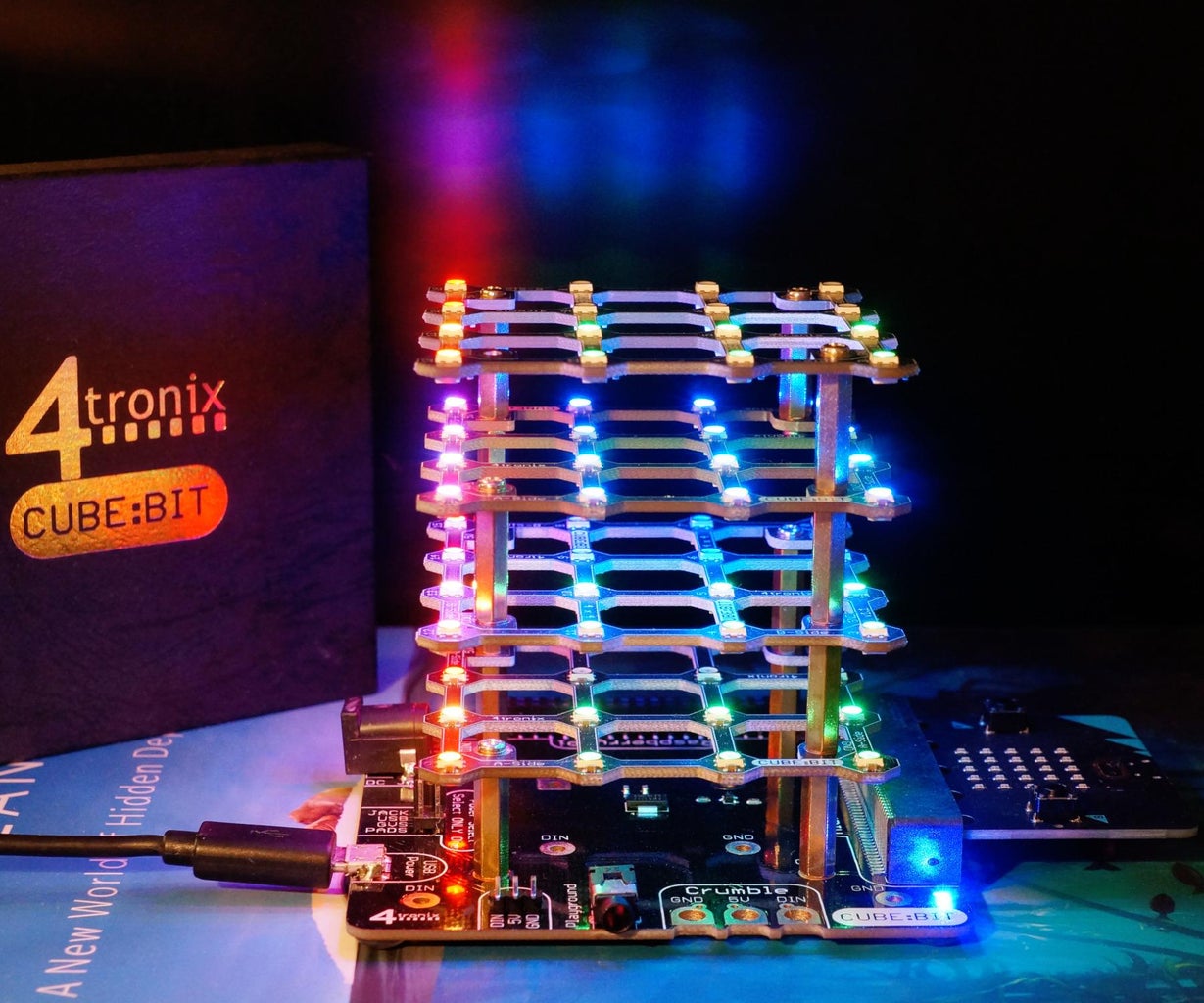
Introduction: MakeCode Fun on the 4tronix Cube:Bit (an RGB LED Cube)


This article provides some examples in MakeCode blocks for controlling the easy-to-build 4tronix Cube:Bit using the BBC micro:bit. The MakeCode system is very easy to use and is attractive for rapid development of small programs. It is a compiled language making it faster in many cases than interpreter based languages like MicroPython/CircuitPython.
The Cube:Bit is a three dimensional array of individually-addressable, multi-coloured LEDs which can be quickly assembled using only a screwdriver. The base offers four options for the 5V power supply for the LEDs and has connectors for the Rapberry Pi (Zero) and the BBC micro:bit for control. The RGB LEDs use the WS2812 protocol and can easily be controlled with libraries which are often named NeoPixel after Adafruit's trademark for these LEDs. There's also a convenient MakeCode extension for the Cube:Bit.
The assembly process might be less satisfying than constructing your own massive LED cube but the screws and standoffs approach is going to be about 40x faster and requires far less expertise. The modular nature of the Cube:Bit allows it be expanded height-wise after construction.
Some of the examples in this article will only run on the V2 micro:bit due to hardware features or code size.
UPDATE: there's now an explanation of how the sound meter code works in this article and some more examples in Rainbows in MakeCode on a 4tronix Cube:Bit (RGB LED Cube).
Supplies
- 4tronix Cube:Bit
- base (works with all size layers): Pimoroni | smalldevices
- 4x4x4 layers (code accommodates any size cube): Pimoroni | smaldevices
- And a small cross-head screwdriver.
- BBC micro:bit V2 Go - Starter Kit (just the board is also ok): Pimoroni | smalldevices
- Suitable 5V power supply - micro USB will be ok for default brightness levels.
Step 1: How Does It Work?

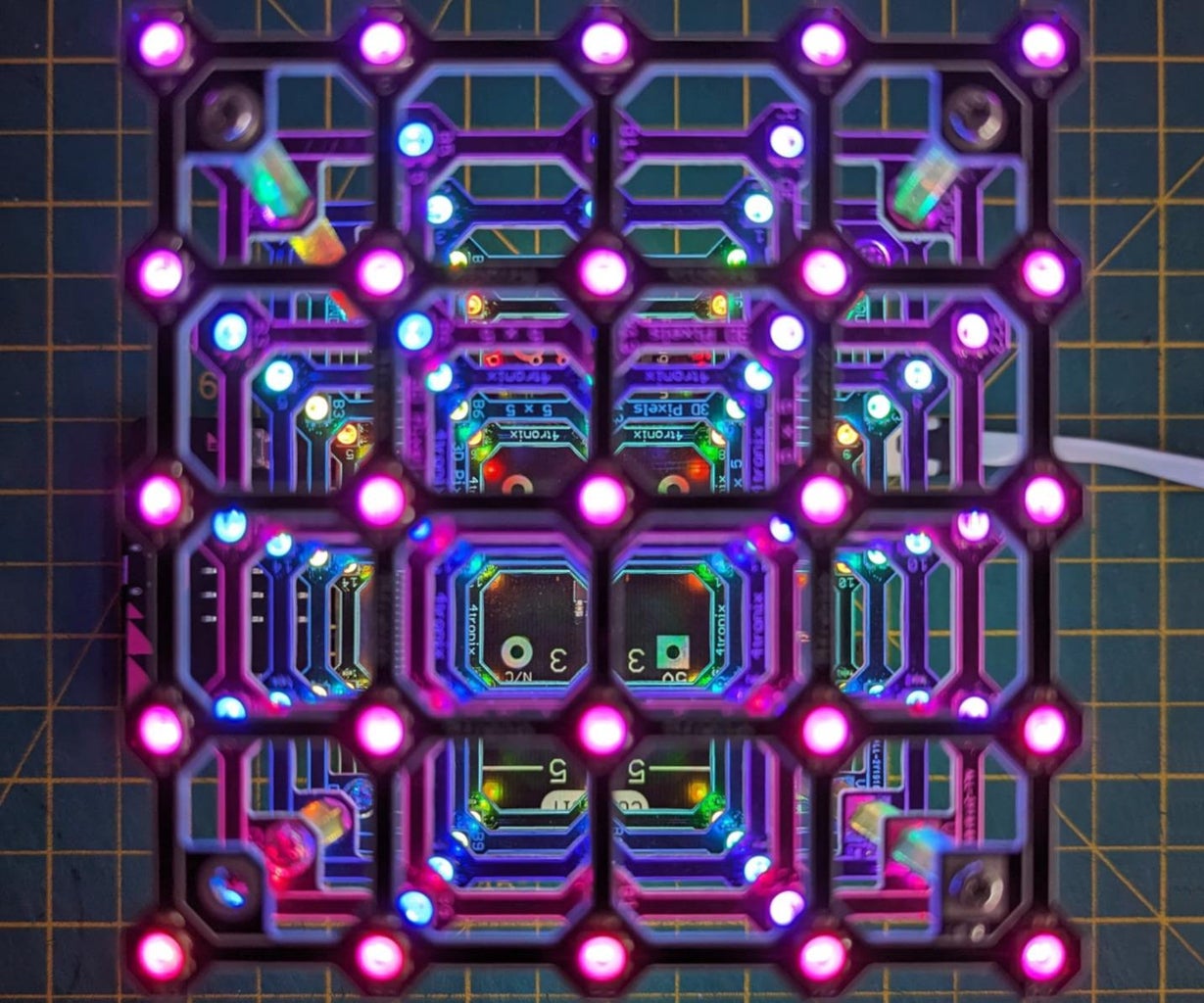
The Cube:Bit is constructed from layers of PCBs which have RGB pixels made from addressable LEDs on the top and the bottom as well as electrical contacts on the inside of the four corners. The WS2812 protocol use a single data pin with the pixels arranged electrically in a long line forming a shift register - the output from the previous pixel connects to the input of the next. Each layer has GND and 5V pads to power the pixels and DIN and DOUT pads to connect them to other layers and the base board.
The 5V power source is selected via jumpers with a choice of:
- 2.1mm barrel jack (centre-positive),
- micro-B USB,
- three male header pins,
- 3 pads with 4mm banana plug holes labelled for the 4tronix Crumble.
As a guide to the power required which can be considerable, 4tronix documents the Cube:bit's typical current requirements as:
- 3x3x3:
- all LEDs at red, brightness 40 (out of 255) = 150mA,
- all LEDs at white, brightness 40 = 340mA,
- all LEDs at white, brightness 255 = 1.9A.
- 4x4x4:
- all LEDs at red, brightness 40 = 350mA,
- all LEDs at white, brightness 40 = 800mA,
- all LEDs at white, brightness 255 = 4.5A.
- 5x5x5:
- all LEDs at red, brightness 40 = 680mA,
- all LEDs at white, brightness 40 = 1.6A,
- all LEDs at white, brightness 255 = 8.75A.
The MakeCode default brightness level is 40 which is surprisingly bright and sufficient for most uses. The 255 level needs to be used with some caution as the Cube:Bit may not be designed for continuous use of all pixels at high brightness levels.
The micro:bit connector has pin 0 connected to pixels. This pin is often used on the micro:bit for audio output to an external piezo speaker so be careful of this clash if using audio libraries.
The 40 pin female header is for a Raspberry Pi Zero and and has GPIO 12 (pin 18) connected to the pixels. A (full size) Raspberry Pi could be used with a suitable cable.
The base board provides 5V power to the Raspberry Pi header and includes a 3.3V regulator to power the micro:bit.
The Cube:Bit has four rubber pads on the base so will not scratch your desk or short out on a metallic surface.
If the Cube:Bit board is unpowered then its regulator appears to partly work in reverse and a powered micro:bit will provide a low voltage (2.54V) to the pixels - this allows the red and green ones to dimly illuminate. This will put a burden on the micro:bit's voltage regulator and should not be used in this way, particularly if lots of pixels are illuminated.
Step 2: Cube:bit Assembly
4tronix have a guide on assembling the Cube:Bit. The essence is remembering that the layers alternate to allow the DOUT of the layer below to connect to the DIN of the layer above. The GND and 5V run in two vertical stacks. The pads on the PCBs are round with the exception of the 5V which is square probably to aid visual identification. With the exception of the bottom layer, all of the layers use three standoffs (spacers) with a gap remaining for the fourth.
Andy Warburton's video above may help a little at 0.25x speed but it's still very fast!
Step 3: Coordinate System

This small program displays the coordinate system for the Cube:Bit. The x, y and z dimensions are shown on the Cube:Bit illuminated with red, green and blue, respectively. The the line drawing starts at the origin (bottom left near the viewer). In MakeCode these are numbered starting from 0. The coordinates for the pixel next to the base's CUBE:BIT logo (near the micro:bit and viewer) is (3,0,0).
This works on V1 and V2 micro:bits.
Step 4: Water (Spirit) Level
This program uses the micro:bit's accelerometer which acts like a plumb line if the device isn't being moved (accelerated). It determines the orientation of the micro:bit and this is used to draw two blue layers to represent the level water. As the Cube:Bit is tilted the water appears to self-level. This is a form of spirit level.
This works well on the V1 and V2 micro:bits.
Step 5: Sound Meter
This program (version 1.0) represents the sound level on the horizontal layers of the Cube:Bit in green with the final layer being amber then red for exceptionally loud sounds.
There are two bug fixes in version 1.1 and the height and sides variables are set to 3 for a smaller cube. These can be set to the appropriate size for your Cube:Bit.
This will not work on the V1 as it does not have a microphone. Kitronik have a useful table comparing the V1 and V2 micro:bits. A good description of the differences is also available in video form by Stu Lowe.
Step 6: Sound Meter Code Explanation Part 1

MakeCode programs can have an on start block which runs once when the program start as the micro:bit is powered on. The orange blocks here are from the Cube:Bit MakeCode extension.
- The VERSION variable isn't used in the program, it's just a highly visible reminder of the version number. This is also embedded in the project name as a -1 suffix. This allows different versions of the program to coexist and be clearly referenceable.
- The height variable is the number of layers present for the Cube:Bit. Despite the naming the Cube:Bit does not have to be a cube, it can have more (or fewer) layers than a cube!
- The set height of tower is the extension block for setting the height. This is only truly required if the Cube:Bit is not a cube.
- The sides variable is the size of each layer which will be the same for all layers as you cannot mix and match!
- The create Cube:Bit block creates the software representation of the Cube:Bit with the appropriate size sides and previously set height. The P0 is for the micro:bit's pad 0 which is used to transmit the data for the pixel settings to the Cube:Bit.
- The update mode is set to Manual (rather than Automatic). This means that changes are not immediately sent to the Cube:Bit and they are only sent when a show block is executed although there are a few other blocks which are exceptions to this. Using an explicit show at the end of a series of related small updates is more efficient and it may reduce flicker for frequent updates.
- The Cube:Bit brightness is a value between 0 and 255 (0 to 2^8-1 is the range of a byte (octet) used as an unsigned 8bit integer) which sets the overall (global) brightness of the Cube:Bit. The default value is 40 is bright in most environments. Lower values can be useful for filming videos as bright RGB pixels can saturate a camera's sensor and end up looking mostly white regardless of colour.
- The REM variable is just an important reminder of how much current is used for different settings based on the 4tronix documentation. REM is a nod to comments in the old computer language BASIC.
The on start block will not run again until the micro:bit's reset button is pressed or the micro:bit is powered off and on.
Step 7: Sound Meter Code Explanation Part 2

MakeCode programs can have a forever block which, as the name suggests, will repeat forever. When all of the blocks inside the forever block have executed it will then move back to the first block and continue execution.
- The sound level block is specific to the V2 micro:bit which has a microphone. It is returning a number which represents the volume between 0 and 255 over a short period of time. The documentation does not specify what these values mean, i.e. they are not a standard sound pressure unit.
- The map block is taking this integer number and remapping it from 0-170 to 0-100. This means 0 will map to 0.0, 20->11.7647, 85->50.0, 170->100.0 and 255->150.0. The min function is being used to limit the value to a maximum of 100 - this means really really loud sounds will always map to 100 and no more. As can be seen from the example of 20 mapping to 11.7647, map produces a real number often called floating-point in computer languages. There's no guarantee of a whole number (integer) being produced for this value.
- The if block is rather pointless as the value is set to true and the code inside will always execute! This technique allows the programmer to quickly change the value to false to stop certain parts of the program executing - this can be useful for debugging without having to keep removing/reinserting code.
- The plot bar graph shows the value on the 5x5 red LED matrix on the micro:bit - map is used again to translate the 0-100 to 0-25 to match the LED count. The serial write part is set to OFF to stop the data being written to the serial console (over USB) as this isn't needed.
- The setCubeVolume procedure (a function with no return value) is called with one numeric argument volume.
It isn't clear why the value of 170 was chosen here. Numbers like these are sometimes referred to as magic numbers. This would be better represented by a variable with an appropriate name, a comment to describe it and some more detailed documentation.
There is no code here to control the speed this forever block executes at. This will be determined by the speed of the processor and how frequently the MakeCode system loops the forever block. The V2 micro:bit has a faster processor than the V1.
MakeCode programs can have more than one forever block and they appear to execute at the same time (concurrently).
Step 8: Sound Meter Code Explanation Part 3

This is the definition of a function called setCubeVolume which takes one (numeric) argument which is called num. Colours are being created here with RGB triplet values between 0 and 255, e.g. red is (255, 0, 0), orange is (255, 128, 0), green is (0, 255, 0) and a very dim green is (0, 13, 0).
- The cube level variable is set with another use of map to a real number between 0 and 4**.
- This function is designed to only work properly if the value is between 0-100 and may misbehave if given numbers outside of that range. If this was formally stated then it would be a design by contract.
- Variable names with spaces in are unusual in computer languages but MakeCode supports them. It's probably best to avoid whitespace in variable names if you are planning to switch to the MakeCode JavaScript or Python dialects.
- clear all pixels (efficiently) sets all the pixels (64 on a 4x4x4) to black.
- The remainder variable is initialised to cube level.
- The for loop now repeats N times where N is the number of Cube:Bit layers - this is represented as 0 to height-1. The index variable will be the layer number starting at 0 where 0 is the bottom of the Cube:Bit.
- The luminance variable is set to an integer value** which will be between 0-255 if the remainder is between 0-1. The largest value will be 1020 (this is 4*255).
- The first if block sets the colour to use. The condition is testing if the loop's index is set to the top layer which is numbered height-1.
- The top layer is special and some mathematical functions are being used to calculate the red and green components of the colour mix. The intent here is to create a graduated scale from black to orange to red to emulate the look of a digital vu meter.
- The other layers are just set to green with the green brightness based on the luminance value.
- The second if block sets the colour of the layer using set plane if the layer needs to be illuminated based on the remainder value - if it's not set then the it will remain unchanged and be black.
- The remainder variable is then decremented by 1.
- After the illuminated layers have had their colour set in the loop the show Cube:Bit changes updates the Cube:Bit in one efficient operation.
Step by Step Example
For an example of a sound level of 106 this will have been mapped to a volume of 62.353. The volume arrives in this function as num and is converted to a cube level of 2.494. The layer loops over the four layers starting at the bottom. The remainder value is used for the quantity of layers to illuminate, the naming reflects the number of layers left to illuminate in the loop.
- Layer 0 (bottom) is intended to be set to full brightness green (0, 255, 0), remainder=2.494.
- Layer 1 is intended to be set to full brightness green, remainder=1.494.
- Layer 2 is set to half brightness green (0, 128, 0), remainder=0.494.
- Layer 3 (top) is left as is (black), remainder=-0.506 (a negative value).
Colour Calculations
For the orange/red calculations used for the top layer, here are some example values of how luminance maps to an RGB triplet.
- 0 -> (0, 0, 0) = off = black.
- 64 -> (64, 32, 0) orange (AKA amber).
- 128 -> (128, 64, 0) orange.
- 192 -> (192, 32, 0) orangey red.
- 255 -> (255, 0, 0) red.
Bugs
There are two bugs present in the version 1.0 code marked with two asterisks** above.
- The "hard-coded" value of 4 needs to be replaced by the global variableheight to allow the code to work properly on different size cubes.
- The luminance variable must be limited to a maximum of 255 as the behaviour of the convert from block is not documented for values above 255. This can be done with a min function or a constrain function around the round when luminance is set. This bug will probably be making the green layers dimmer and more flicker-prone than they should be.
Improvements
There's also at least one minor optimisation.
- Once the remainder is negative there's no more work to be done and the loop could be ended early with a break block. An alternative approach is to set these remaining layers to black and remove the clear all pixels.
Step 9: Oscillating and Rotating RGB Planes
This program was inspired by the code from the water level program and moves three flat planes through the cube. It originally had two modes, one which oscillates the planes back and forth in each dimension (this is similar to a 4tronix example) and another which rotates them near the origin. The third mode was added later and is shown below.
This works on V1 and V2 micro:bits. The update rate is a little lower on the V1 but still acceptable.
Step 10: Settling RGB Planes
This is a revised version of the program used for the previous video which now offers a third mode with planes which move along the z axis (up and down) and then settle to resting positions.
This works on V1 and V2 micro:bits. The update rate is a little lower on the V1 but still acceptable.
Step 11: Cubetris - a Tetris Like Game
Cubetris is a version of the popular Tetris game with an extra dimension. A complete Cubetris game can be seen above, the monochrome Tetris game is just a background.
- The micro:bit's right B button starts the game.
- The blocks will fall as far as they can and can be moved by tilting the cube and spun using the same button.
- When a layer is completely full it will disappear and pieces settled above will fall down.
- The game finishes when no more pieces fit on the cube - the score is displayed (twice) on the micro:bit's display.
- The music can be muted and unmuted by pressing the gold logo on the micro:bit.
This code is too large for the V1 micro:bit. The block editor in a browser can struggle with this size code. This is probably slightly beyond the sensible size and complexity for a MakeCode block project. MakeCode offers translation to JavaScript and Python - one of these alternative dialects would be more suitable.
There's a bug somewhere which causes the game to freeze approximately 1 game in 15. This could be in the program or in MakeCode.
Step 12: Going Further
The photograph above is from AlwaysComputing on Twitter.
Hopefully the examples in this article provide some further ideas for programming your Cube:Bit or some inspiration to build/assemble your own LED cube.
The source code is presented as links on each page and can also be found on GitHub as hex files with the associated JavaScript (Static TypeScript).
Related projects and kits:
- 4tronix Cube:Bit examples - scroll to the bottom for Example Software section. These hex files are for the V1 micro:bit and will fail to install with a 529 error on a V2. For the V2 they can opened in the MakeCode editor and easily recompiled in a few seconds.
- Robin Newman Blog: 4tronix 5×5 CubeBit controlled by Sonic Pi
- BlinkyParts 3x3x3x LED cube - these LEDs aren't programmable but it's a good way to get some experience of cube building.
- Adafruit Learn: Free-Wired 3x3x3 NeoPixel Cube
- Lorraine McUnderwood's blog posts relating to her 8x8x8 LED cube
- Instructables: LED Cube 8x8x8 - one of the many on Instructables - also described on Jameco Electronics: How to Build an 8x8x8 LED Cube - this is a lot of work and requires some practice and skill to implement.
- Malt Whiskey: How to make a 16x16x16 LED CUBE at home with Arduino platform (YouTube) - a very impressive 16x16x16 RGB LED cube controlled with a Teensy 4.0 microcontroller with some great animations.
Further reading:
- Squidsoup: LED Cubes - An Anthology
- Make: World's Biggest LED Cube?
- Adafruit Learn: Adafruit NeoPixel Uberguide
- Instructables: RGB LED Current Measurement With Nordic Power Profiler Kit II - a look at how RGB LEDs consume current including an example of the 10 NeoPixels on a Circuit Playground Bluefruit.


![Tim's Mechanical Spider Leg [LU9685-20CU]](https://content.instructables.com/FFB/5R4I/LVKZ6G6R/FFB5R4ILVKZ6G6R.png?auto=webp&crop=1.2%3A1&frame=1&width=306)


