

Introduction: Neopixel Brass Circuit Sculpture Lamp


I'm fond of circuit sculptures and often get inspired by others' to build mine.
This was the case for this one.
I got inspired by this very nice LED cube
This is actually my second circuit sculpture based on this LED cube (the first one is here). I wanted to give a try to the cube version, adding my own take to it (I used an ATTiny and changed the way the LED carousel is built).
I enjoyed the software side too, the various color animation modes, and only did some minor changes in my version:
- I slowed-down the animations (I like slow moving color transitions)
- I added a persistent memory of the current animation mode (stored in EEProm).
- I refactored and cleaned-up the code.
My code, is, of-course, opensource, available on my Github.
I'm not completely satisfied with my build. It looks a bit clunky. But I've learnt lessons to build better ones in the future.
Supplies
What you will need to build this thing:
- an ATTiny 85 (or whatever you want that can drive WS1812 LED).
- a 100nF capacitor (not really needed but that's a good practice)
- about 30cm of 1mm-thick brass rod
- about 1.30m of 1.5mm-thick brass rod
- 4 NeoPixels (WS2812 LED on a small breakout board)
- (optional) an ILS switch, or any other micro-switch
Step 1: Programming the ATTIny85

There are plenty of tutorials online on how to program an ATTiny85 with the Arduino IDE.
Something you must take care of with this build:
Select the board config ATTiny85 with Internal Clock @ 8 MHz
Use the "Burn Bootloader" command, in order to set the internal fuses for the ATTiny to run at 8MHz. Otherwise the sketch won't run (well, it will run but the LED won't light-up).
I'm using an USBasp programmer, cheap and efficient, but you may also use an Arduino as ISP.
You can change the number of LED in the code from the de default 8 to 4, however this won't change anything (this will only sligthly optimise the data transmission to the LED).
Step 2: The Outer Cube


The base cube provides the structure and ground connection of the lamp.
Base and Top Squares
I've used a 3D-printed 60x60mm plate as a rig to form the top and bottom squares. I chose to build a 63x63mm outer cube, this seemed to be a good size to me (It can easily be made 15mm smaller).
Using a template square drawn on a paper sheet is also OK.
However, you'd better not place the soldering joint in the middle of a side as I did. The soldering joint should be at about 1/3rd of the side length, this will make soldering the LED ground connection easier (since it will be soldered at the middle).
Make sure your squares are flat and the same dimension. This is critical for a nice final look.
Sides
The sides are made of 4 60mm brass rods
As shown in the photo I've used a piece of plywood, shapened on one side and temporarily hot-glued at each corner of the base square, to provide a rig to maintain the side rods vertical while soldering them to the bottom square.
I then used a helping-hand stand to maintain the top square while soldering.
Step 3: Connecting the ATTiny


This is actually the easy part of this build.
In order to avoid short-cuircuits when using the lamp on metallic surfaces, the ATTiny is up 5mm from the base.
It's maintained centered in position during soldring using a small piece of 5mm plywood.
I flattened the pins of the ATTiny and cut the tips of the pins.
The ground connection to pin 4 is soldered first, to the base square.
The color mode selection touch switch is connected to pin 2 and placed near a ground line. I chose to use a L-shaped brass rod. Its short side must not touch the ground connection on the base square. It's left about 1mm up the base square.
Pin 8 is connected to VCC. I chose to use an ILS switch with a little sliding magnet, because I had one laying around and I like ILS switches, but you may choose to use anything else, or no switch at all.
I had a scavenged micro barrel power socket and plug handy too.
The only 100nF capacitor I had was scavenged on a PCB so I had to find somewhere I could solder it with its short pins. It should have been located as close as possible to the ATTiny.
Before going further I made sure everything was OK by temporarily connecting a Neopixel bar. The first 4 or 8 LED should light-up (depending whether you changed the default number of LED in the software).
Step 4: The LED Carousel - the 5V and Data Rails


This is the most difficult part in this build.
The 5V Rail
I wanted the LED carousel to occupy about 2/3rd of the surface, so I chose to build a 35x35mm square for the 5V rail.
I did not use any rig. I just marked each segment and used pliers to form the square.
Here again I should have started the square from 1/3rd of a side length instead of the middle. This would have made soldering the LED easier.
Indeed the Neopixel are soldered to the 5V rail, at the middle of each side and soldering the LED on the square joint proved painful.
I've used a helping-hand stand to maintain the 5V rail while sodering the LED VCC pins on it and, well,.. it would have been way easier to maintain the LED in a small vise to solder them perpendicular to the 5V rail.
The Data Rail
I chose to use 1mm brass for the data rail. This is much easier to work with than 1.5mm brass.
Each section of the data rail is a L-shaped rod, connected between the Data-Out and Data-In pins of 3 of the 4 Neopixels.
I tried to get an even spacing between the 5V and data rails.
Before the next step, double-check the solders and make sure there is no short between the 5V rail and the data-rail segments.
Step 5: The LED Carousel - Attachment to the Ground Line

Each Neopixel is connected to GND via a L-shaped brass rod soldered on the top square.
I first measured the distances and determined the dimensions of the L-shaped rods in order to have the LED carousel centered, and down 15mm.
I then soldered the first connection to the top square manually, using only pliers to maintain the piece in position while soldering. This proved difficult :)
I should have reversed the cube and use a small rig to maintain the pieces vertical, much like the one I had used to solder the cube vertical segments.
Anyway, after a lot of trial and errors I finally got the LED carousel properly centered and parallel to the top cube side.
Attention: take care of orienting the LED carousel such as the first Neopixel (the one with nothing soldered on its data-in pin) is on the same side as the ATTiny Pin 3.
Step 6: The LED Carousel - Power and Data Connections

The 5V rail is connected to VCC via a vertical L-shaped rod.
I've soldered it between the ILS switch and pin 1 of the ATTiny, in order to avoid soldering multiple connections on one location.
The data line is made of a piece of pre-formed 1mm brass rod going up from pin 3 to the Data-in pin of the first Neopixel.
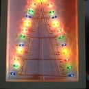
That's it! Power-on and enjoy!

![Tim's Mechanical Spider Leg [LU9685-20CU]](https://content.instructables.com/FFB/5R4I/LVKZ6G6R/FFB5R4ILVKZ6G6R.png?auto=webp&crop=1.2%3A1&frame=1&width=306)


