

Introduction: DIY Arduino Wristwatch Walkie-Talkie


Alrighty, I have always wanted to make a wristwatch walkie-talkie to emulate the communicators used in Mighty Morphin Power Rangers. My interest has recently been rejuvenated after finding a cool Power Rangers communicator prop and by the recent development of voice calls with smartwatches. I have been doing a bit of prototyping on-and-off for a while now and I think I have an idea of what I want to do. In this Instructable, I will show you guys how to put together a simple walkie-talkie using the nRF24L01. TMRh20 has put together a nice audio transmission library using the nRF24. I am a ways away from making a well put together device, but I got a kick out of coming this far in the process and I hope you will too.
Step 1: Gather Your Tools
I wanted to make this prototype relatively sleek, so I was trying to solder everything to a protoboard. That did not work out so well. I also want to submit this Instructables in the Wearables Tech Contest, which ends tonight. So, here goes plan B. There is a lot more miniaturization to come.
2 x Arduino UNO/SparkFun RedBoard (An Arduino Mega could also be used)
2 x nRF24L01 (originally purchased on eBay, but SparkFun now carries a version and I would recommend buying it from them, though I have not tried their version)
2 x electret microphone (originailly purchased on Amazon and got a few cheap mics. Decent purchase. If you want something better, I'd recommend this)
2 x NPN transistor
2 x Buttons
2 x 3.5 mm jack breakout
2 x Breadboard
6 x 10 k resistor
2 x 100 k resistor
6 x 100 nF capacitor
Assorted jumper wire in particular, you need some that are male-female for connecting the nRF24L01 to the Arduino. The nRF24L01 module is not breadboard friendly.
Tools
- Soldering iron
- Solder
- Flux pen
- Soldering wick
Step 2: Microphone Circuit


datasheet from ON SemiconductorThe microphone circuit is pretty simple really. I do not know the original source of the circuit. I happened upon it when Googling "simple microphone circuit." I included the original picture because I wanted to give credit to the original poster (whoever that may be), but I made a slight change. I removed the 0.1 uF capacitor at the collector of the transistor. This capacitor filters out DC voltages and only passes AC currents which means that we will be creating "negative" voltages. This is fine in most cases, but since we are connecting the output of the preamp to our microcontroller, we can't pass a "negative" voltage. It also allows us to hook our pre-amp circuit directly to headphones, but since we are connected it to the analog-to-digital converter of the Arduino, we can remove it.
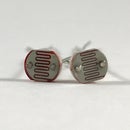
Electret Microphone and Transistor
These electret microphones have a flexible diaphragm on the inside that moves based on the sound wave that hits them. The diaphragm is parallel to another conducting plate which creates a capacitor with variable capacitance based upon the flexing of the diaphragm and subsequently the sound pressure wave that the microphone is picking up. With the microphone connected to the circuit the way it is, it will produce an AC current at the base of the transistor based upon the sound wave hitting the microphone. The base current of the transistor is amplified and so we have an amplified sound wave that we are feeding into our microcontroller.
The pinout for the transistor is attached. The image is courtesy of the datasheet from ON Semiconductor <http://www.onsemi.com/pub_link/Collateral/2N3903-D.PDF>
Step 3: Call Button

We need a simple button circuit for calling the person on the other end of the walkie talkie. I used a simple pushbutton, 10 k resistor, and a 100 nF capacitor. The circuit is pretty straightforward. I added a capacitor to the typical button circuit that you may be familiar with. This capacitor is to help prevent "bouncing" or erratic signals from the button. You may be familiar with other ways to debounce a button, but I have found that adding the capacitor works well enough.
I have attached an interrupt to pin 3 to detect when the button is pressed. Interrupts are really nifty. They allow us to "interrupt" the code to provide very precisely timed events without deteriorating performance (if done properly).
attachInterrupt(digitalPinToInterrupt(talkButton), talk, CHANGE);
With this piece of code, we go to the "talk()" function which checks the voltage on pin 3. If the voltage is HIGH or 5 V, the nRF24L01 will switch to transmit mode (sending voice). If the voltage is LOW or 0 V, the nRF24L01 will switch to receive mode (receiving voice). The voltage on pin 3 should be HIGH when the button is pressed and LOW when the button is released. Whenever the voltage on pin 3 "CHANGES" as denoted in our "attachInterrupt" function, the "talk()" function will execute.
void talk()<br>{<br> if (digitalRead(talkButton)) rfAudio.transmit();<br> else rfAudio.receive();<br>}Step 4: Add Speaker


TMRh20's RF24 Audio library hardwires the speaker outputs to pins 10 and 9 on the Arduino. You can simply connect these to a small speaker or headphones without a pre-amp. For bigger speakers you would want to use a pre-amp, or maybe for long-term use. I used some alligator clips to connect pins 10 and 9 to the 3.5 mm headphone jack. I also used SparkFun's 3.5 mm Jack Breakout which was extremely handy.
Step 5: Wireless Transmission


nRF24L01 to Arduino
1. Ground to Ground
2. Vcc to 3.3 V (NOT 5 V)
3. CE to digital pin 7
4. CSN to digital pin 8
5. SCK to digital pin 13
6. MOSI to digital pin 11
7. MISO to digital pin 12
8. IRQ to digital pin 2
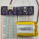
I used the nRFL01 RF transceiver from Nordic Semiconductor for this project. This guy is a pretty popular hobbyist RF transceiver due to its low cost and decent range. I used the long ranged modules (with the antenna), but these are not necessary. For this step, we need to download two Arduino libraries: the RF24 and the RF24Audio library (attached). For instructions on installing 3rd party libraries for the Arduino, please refer to this tutorial at Arduino.cc. Also attached is the pinout for the nRF24L01 courtesy of Terry King and the other contributors of the ArduinoInfo.Info Wiki. Terry also has a detailed tutorial and description for the nRF24L01 that I found very helpful. Check it out. I also soldered 100 nF capacitors across Vcc and GND for stability, as recommended by Terry King in his wiki. Also notice that the nRF24L01 is a 3.3 V device, not 5 V. The other pins are 5 V tolerant, but Vcc is not.
Attachments

Step 6: Arduino Code
I put together a simple code utilizing the RF24 and RF24Audio libraries. Pretty simple. Upload this code to both Arduinos. Both circuits with default to "receive" at the start of the code. Press the "call button" to transmit audio from one radio to the other. NOTE: The RF24Audio is using PWN and some other techniques to transmit audio. This produces loud background noise that is pretty irritating. I have not figured out how to get rid of that as yet. If you do, please share!
Alrighty, have fun!
You can download the walkie talkie code from its GitHub Repository or from the attachment below.
Attachments

Participated in the
Wearable Tech Contest

Participated in the
Tech Contest

Participated in the
Spectacular Failures Contest


![Tim's Mechanical Spider Leg [LU9685-20CU]](https://content.instructables.com/FFB/5R4I/LVKZ6G6R/FFB5R4ILVKZ6G6R.png?auto=webp&crop=1.2%3A1&frame=1&width=306)


