

Introduction: DIY Arduino Pulse Sensor


So I mentioned in an earlier Instructable that I am a teaching assistant (TA) for an introductory engineering course for biomedical engineering majors at Vanderbilt University. My main task as a TA is to re-write a few laboratory exercises that the students will be performed during the class. One of the laboratory exercises was to implement a simple circuit to measure the someone's heart rate using photoplethysmography.
As blood is pumped through the body, the volume of blood in extremities such as your fingers increases and decreases with the pumping of the heart. The change in blood volume in the finger tips can be detected by shining a light through the finger and detecting the amount of light that passes through the finger using a photodiode. A photodiode is semiconductor that produces a current proportional to the amount of light that hits it. So when the blood volume in the fingers increases, less light is getting through the finger and hitting the photodiode.
The current produced by the photodiode is converted to a voltage by an amplifier and read by the Arduino. Here we go! I hope you enjoy reading and building!
*****NOTE: This is NOT a medical device.
Step 1: Gather Your Tools
*****NOTE: This is NOT a medical device.
You will need
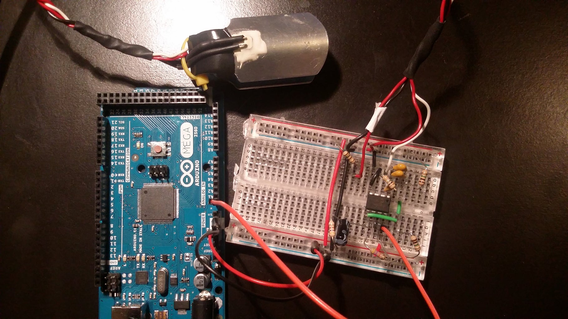
1 x Arduino (of course) (https://www.seeedstudio.com/Arduino-Mega2560-Rev3-p-695.html)
1 x General Purpose Op Amp
5 x Resistors
3 x Capacitors
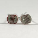
1 x Photodiode
1 x IR LED
For the general purpose op amp, I used an MCP6002 which can be purchased from any major electronics distributor such as DigiKey.com, Mouser.com, or Newark.com. I purchased mine from Newark. I liked this op amp because it is single supply, meaning it only needs to be powered using ground (GND) and a positive voltage. It does not need a negative voltage supply like many other op amps. This enables it to be easily integrated with the Arduino which only runs on a positive supply. If you use a bipolar op amp, you have to make sure the op amp and Arduino are running on the same GND and positive supply. Do not connect the negative supply to the Arduino. You will fry something on it. I have done it before.
The resistor values that you will need are as follows:
3 x 1 MOhm resistors
1 x 10 kOhm resistor
1 x 1 kOhm resistor
The capacitor values that you will need are as follows:
1 x 10 nF
1 x 560 nF (I ended up using a 470 nF and 100 nF in parallel - which adds us to 570 nF - which is close enough)
For the photodiode and IR LED, the Bio-Instrumentation lab at Vanderbilt University made a few finger cuffs with integrated photodiode and IR LED, so we used those for the lab. You can purchase disposable finger cuffs online. You can make your own as well. You just need some sort of housing for the photodiode and IR LED to keep them really steady on someone's finger.
Step 2: Summary of Operation
As the heart pumps blood through the body the volume of blood in extremities such as the fingers increases and decreases. We can detect the change in blood volume in the fingertips by shining a light through the finger and detecting the amount of light that passes through the finger using a photodiode.
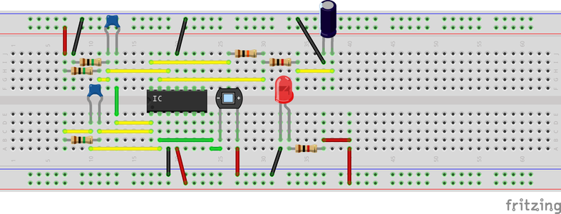
Step 3: Circuit Diagram
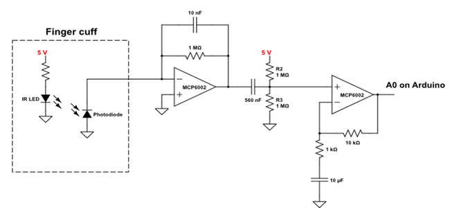

We will be creating the circuit depicted in the corresponding image. The circuit has three main parts:
- Finger cuff
- Transimpedance stage
- High-pass filter
- AC gain-stage
I will explain these various parts in the next sections.
Step 4: Finger Cuff

As I stated before, the finger cuff has a photodiode (I don't know the part number) and IR LED integrated into it. Both components have wires that connect them to the Arduino.
Please see Notes 1 and 2 in "Step 10: Troubleshooting."
Step 5: Transimpedance Amplifier

The next portion of our circuit is what is known as a transimpedance amplifier or current-to-voltage converter. A transimpedance amplifier is an amplifier configuration that allows us to convert a current to a voltage. In our case, the current produced by the photodiode flows through the resistor in the op amp's feedback loop. We will see a voltage at the output of the op amp with accordance to Ohm's Law, V = I*R. The current produced by a photodiode can be pretty small (micro-amps), so this is why we are using such a large resistor (1 MOhm) as the gain-setting resistor. A high gain-resistor such as this is typical for transimpedance amplifiers. The capacitor in the feedback loop helps reduce high-frequency noise.
Please see Note 2 in "Step 10: Troubleshooting."
Step 6: High Pass Filter

Our next stage is a high-pass filter. A high-pass filter allow us to remove low-frequency signals. In our case, we are removing signals that are slower than a normal pulse signal. Specifically, we are removing the DC bias from our signal. When the IR LED shines light through the finger, most of the light is absorbed by the tissue. Our circuit will in turn produce a voltage that corresponds to the absorbance of light by the tissue, not the pulsatility of the artery (which is what we really want). For this reason, we use a high pass filter to get only the absorbance due to the pulsatility of the blood in the arteries (our pulse).
Step 7: AC Gain Stage

The final portion of our circuit is an AC gain stage using a non-inverting op amp. A non-inverting op amp amplifies and input voltage in accordance to the equation 1+R2/R1 where R2 is the resistor in the feedback loop and R1 is the resistor that is connected to ground. Notice the capacitor in the our non-inverting op amp. A capacitor blocks DC signals and only allows AC signals to pass. This means that only the AC signal which corresponds to our pulse gets amplified, not the Vref voltage that we applied in the previous stage.
This was a neat little circuits trick that was pointed out to me by MattDougan. Check his page out if you get a chance.
The signal at the output of our AC gain stage is read by the analog-to-digital converter on our Arduino.
Please see Note 4 in "Step 10: Troubleshooting."
Step 8: Software Interface
For the class that I am TA-ing for, I actually wrote a LabVIEW VI for this circuit. LabVIEW is a pretty powerful engineering program that allows for automation of experiments, data visualization, etc. It is extremely useful, but unfortunately proprietary so the average person does not have access to it. For this reason, I have slightly modified the Arduino graphing example in Processing so that it will plot the pulse waveform. This Instructable is still a work in progress and there are a lot of things I would like to change. I would like to create a custom user interface for the viewing the pulse waveform, as well as the heart beat, but this should be pretty good for now. Included are the Arduino, Processing, and LabVIEW codes.
Enjoy!
If you have any questions, please feel free to ask.

Step 9: A Few Screenshots


Step 10: Troubleshooting

After speaking with a few people who had problems getting the sensor to work, I have put together a list of common pitfalls and how to remedy them.
- The positioning of your finger between the LED and photodiode is very critical to obtaining a stable signal. For the class that I developed this circuit for, we had the LED and photodiode fixed in a finger splint (as seen in the intro picture), which ensured stability.
- You may need to decrease the brightness of the LED. With your set up, check the output of the transimpedance amplifier (Step 5). It should be within your power rails (lower than 5V and greater than 0V if powering with +5V and GND)
- You may need to add more gain to your pulse sensor circuit. I would suggest this gain stage
https://www.circuitlab.com/circuit/jp7tu98zj5x6/pu... - The high pass filter created by the 1k resistor and 10uF capacitor (Step 7) is not very well tuned for the pulse frequency. The cut-off frequency for the 1k resistor and 10uF capacitor is about 16Hz which is well above the pulse frequency of 1.2Hz. Unfortunately, I simply overlooked this when first making the circuit. That being said, the circuit still worked really well. I created several of them for the class I was TA-ing for and the students were able to get really good pulse data (Step 9). I think having the LED and photodiode enclosed in a finger splint really improved signal integrity which offsetted the effects of the miscalculated cut-off frequency. As a result, I think adding the extra gain stage as suggested in point 3 (above) should help correct for the miscalculated cutoff frequency. You could also modify the RC values for the high pass filter to be 1uF and 330k to create a high-pass filter cutoff of 0.5Hz, which will help preserve our pulse signal. Accordingly, you should change the value of the 10k resistor to be at least 330k. Any value higher than 330k will give you a pulse signal gain that is equal to the ratio of the two resistors.
- Also the LabVIEW GUI does have a few bugs in it when it comes to reading in serial data, so it's a bit finicky. If you know how to properly set up the serial connection settings in LabVIEW, please share. Otherwise, the Processing GUI should work, it just looks boring. All else fails, the Serial Plotter option in Arduino would be the easiest. The Serial Plotter didn't exist when this project was first built.

Participated in the
Microcontroller Contest

Participated in the
Make it Glow!


